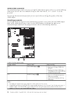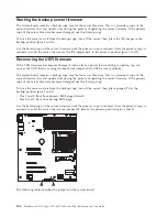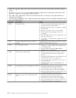
Table 16. System board jumpers
Jumper number
Jumper name
Jumper setting
JP1
Clear CMOS jumper
1
v
Pins 1 and 2: Keep CMOS data
(default).
v
Pins 2 and 3: Clear CMOS data
(including power-on password and
administrator password)
JP6
Boot block jumper
2
v
Pins 1 and 2: Boot from primary
BIOS page (default) .
v
Pins 2 and 3: Boot from backup
BIOS page.
Notes:
1.
If no jumper is present, the server responds as if the pins are set to 1 and 2.
2.
Changing the position of the UEFI boot recovery jumper from pins 1 and 2 to pins 2 and 3 before the server is
turned on alters which flash ROM page is loaded. Do not change the jumper pin position after the server is
turned on. This can cause an unpredictable problem.
Using the integrated management module
The integrated management module (IMM) is a second generation of the functions that were formerly
provided by the baseboard management controller hardware. It combines service processor functions,
video controller, and (when an optional virtual media key is installed) remote presence function in a
single chip.
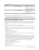
The IMM supports the following basic systems-management features:
v
Environmental monitor with fan speed control for temperature, voltages, fan failure, and power supply
failure.
v
DIMM error assistance. The Unified Extensible Firmware Interface (UEFI) disables a failing DIMM that
is detected during POST, and the IMM lights the associated system error LED and the failing DIMM
error LED.
v
System-event log (SEL).
v
ROM-based IMM firmware flash updates.
v
Auto Boot Failure Recovery (ABR).
v
A virtual media key, which enables remote presence support (remote video, remote keyboard/mouse,
and remote storage).
v
Nonmaskable interrupt (NMI) detection and reporting.
v
Automatic Server Restart (ASR) when POST is not complete or the operating system hangs and the
operating system watchdog timer times-out. The IMM might be configured to watch for the operating
system watchdog timer and reboot the system after a timeout, if the ASR feature is enabled. Otherwise,
the IMM allows the administrator to generate a nonmaskable interrupt (NMI) by pressing an NMI
button on the system board for an operating-system memory dump. ASR is supported by IPMI.
v
Intelligent Platform Management Interface (IPMI) Specification V2.0 and Intelligent Platform
Management Bus (IPMB) support.
v
Invalid system configuration (CNFG) LED support.
v
Serial port redirection over Telnet or SSH.
v
Serial over LAN (SOL).
v
Query power-supply input power.
v
PECI 2 support.
v
Power/reset control (power-on, hard and soft shutdown, hard and soft reset, schedule power control).
Chapter 7. Configuring the server
105
Summary of Contents for 653417U
Page 1: ...Installation and User Guide ThinkServer RS210 Machine Types 6531 6532 6533 and 6534 ...
Page 2: ......
Page 3: ...ThinkServer RS210 Types 6531 6532 6533 and 6534 Installation and User Guide ...
Page 8: ...vi ThinkServer RS210 Types 6531 6532 6533 and 6534 Installation and User Guide ...
Page 16: ...xiv ThinkServer RS210 Types 6531 6532 6533 and 6534 Installation and User Guide ...
Page 20: ...4 ThinkServer RS210 Types 6531 6532 6533 and 6534 Installation and User Guide ...
Page 22: ...6 ThinkServer RS210 Types 6531 6532 6533 and 6534 Installation and User Guide ...
Page 40: ...24 ThinkServer RS210 Types 6531 6532 6533 and 6534 Installation and User Guide ...
Page 66: ...50 ThinkServer RS210 Types 6531 6532 6533 and 6534 Installation and User Guide ...
Page 128: ...112 ThinkServer RS210 Types 6531 6532 6533 and 6534 Installation and User Guide ...
Page 160: ...144 ThinkServer RS210 Types 6531 6532 6533 and 6534 Installation and User Guide ...
Page 164: ...148 ThinkServer RS210 Types 6531 6532 6533 and 6534 Installation and User Guide ...
Page 173: ...Chinese Class A warning statement Korean Class A warning statement Appendix B Notices 157 ...
Page 174: ...158 ThinkServer RS210 Types 6531 6532 6533 and 6534 Installation and User Guide ...
Page 179: ......
Page 180: ...Printed in USA ...

