v
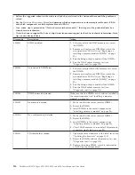
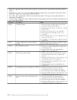
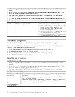
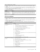
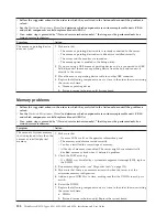
Follow the suggested actions in the order in which they are listed in the Action column until the problem is
solved.
v
See the
Hardware Maintenance Manual
to determine which components are customer replaceable units (CRUs)
and which components are field replaceable units (FRUs).
v
If an action step is preceded by “(Trained service technician only),” that step must be performed only by a
trained service technician.
v
Go to the Lenovo support Web site at http://www.lenovo.com/support to check for technical information, hints,
tips, or new device drivers.
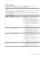
Error code
Description
Action
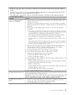
0058007
DIMM population is unsupported.
1.
Make sure the installed DIMMs follow the
population rules and sequence described in
“Installing a memory module” on page 36.
2.
Reseat the DIMMs, and then restart the server.
3.
Remove the lowest-numbered DIMM pair of
those that are identified and replace it with an
identical pair of known good DIMMs, then restart
the server.
4.
Return the removed DIMMs, one pair at a time,
to their original connectors, restarting the server
after each pair, until a pair fails. Replace the
DIMMs in the failed pair with identical known
good DIMMs, restarting the server after each
DIMM is installed. Replace the failed DIMM.
Repeat this step until you have tested all removed
DIMMs.
5.
(Trained service technician only) Replace the
system board.
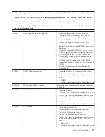
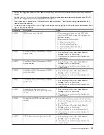
0058008
DIMM failed memory test.
1.
Reseat the DIMMs, and then restart the server.
2.
Replace the following components one at a time,
in the order shown, then restart the server after
each:
a.
DIMM
b.
(Trained service technician only) System board
00580A4
Memory population changed.
Information only. Memory has been added, moved,
or changed.
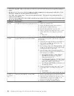
0068002
CMOS battery cleared.
1.
Reseat the battery.
2.
Clear the CMOS memory (see Table 4 on page 20).
3.
Replace the following components one at a time,
in the following order, restarting the server after
each one:
a.
Battery
b.
(Trained service technician only) System board
2011001
PCI-X PERR
1.
Check the riser-card LEDs.
2.
Reseat all affected adapters and riser cards.
3.
Update the PCI adapter firmware.
4.
Remove the adapter from the riser card.
5.
Replace the following components one at a time,
in the order shown, restarting the server each
time:
a.
Riser card
b.
(Trained service technician only) System board
Chapter 8. Solving problems
117
Summary of Contents for 653417U
Page 1: ...Installation and User Guide ThinkServer RS210 Machine Types 6531 6532 6533 and 6534 ...
Page 2: ......
Page 3: ...ThinkServer RS210 Types 6531 6532 6533 and 6534 Installation and User Guide ...
Page 8: ...vi ThinkServer RS210 Types 6531 6532 6533 and 6534 Installation and User Guide ...
Page 16: ...xiv ThinkServer RS210 Types 6531 6532 6533 and 6534 Installation and User Guide ...
Page 20: ...4 ThinkServer RS210 Types 6531 6532 6533 and 6534 Installation and User Guide ...
Page 22: ...6 ThinkServer RS210 Types 6531 6532 6533 and 6534 Installation and User Guide ...
Page 40: ...24 ThinkServer RS210 Types 6531 6532 6533 and 6534 Installation and User Guide ...
Page 66: ...50 ThinkServer RS210 Types 6531 6532 6533 and 6534 Installation and User Guide ...
Page 128: ...112 ThinkServer RS210 Types 6531 6532 6533 and 6534 Installation and User Guide ...
Page 160: ...144 ThinkServer RS210 Types 6531 6532 6533 and 6534 Installation and User Guide ...
Page 164: ...148 ThinkServer RS210 Types 6531 6532 6533 and 6534 Installation and User Guide ...
Page 173: ...Chinese Class A warning statement Korean Class A warning statement Appendix B Notices 157 ...
Page 174: ...158 ThinkServer RS210 Types 6531 6532 6533 and 6534 Installation and User Guide ...
Page 179: ......
Page 180: ...Printed in USA ...

