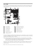
v
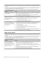
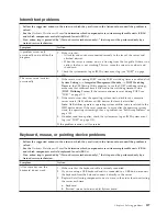
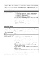
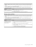
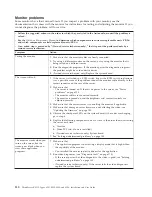
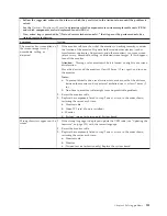
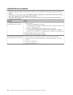
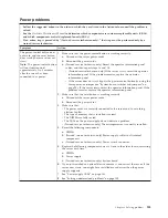
Follow the suggested actions in the order in which they are listed in the Action column until the problem is
solved.
v
If an action step is preceded by “(Trained service technician only),” that step must be performed only by a
trained service technician.
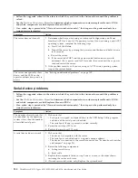
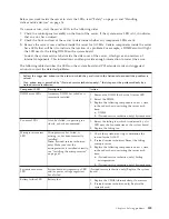
Component LED
Description
Action
IMM heartbeat LED
Indicates the status of the boot
process of the IMM.
When the server is connected to
power this LED flashes quickly to
indicate that the IMM code is
loading. When the loading is
complete, the LED stops flashing
briefly and then flashes slowly to
indicate that the IMM if fully
operational and you can press the
power-control button to start the
server.
If the LED does not begin flashing within 30 seconds
of when the server is connected to power, complete
the following steps:
1.
(Trained service technician only) Rerecover the
firmware (see “Recovering the UEFI firmware” on
page 104).
2.
(Trained service technician only) Replace the
system board.
PCI slots error LEDs
An error has occurred on a PCI bus
or on the system board. An
additional LED is lit next to a
failing PCI slot.
1.
Check the system-event log for information about
the error.
2.
If you cannot isolate the failing PCI card through
the LEDs and the information in the system-event
log, remove one PCI card at a time, and restart the
server after each PCI card is removed.
3.
If the failure remains, go to http://
www.lenovo.com/support for additional
troubleshooting information.
H8 heartbeat LED
power-on and power-off
sequencing.
1.
If the LED flashes at 1Hz, it is functioning
properly and no action is necessary.
2.
If the LED is not flashing, (trained service
technician only) replace the system board.
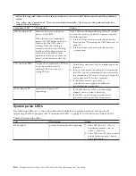
System pulse LEDs
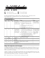
The following LEDs are on the system board and indicates the system power-on and power-off
sequencing and boot progress (see “System-board LEDs” on page 21 for the location of these LEDs).
Table 18. System pulse LEDs
LED
Description
Action
H8 heartbeat
power-on and power-off sequencing.
1.
If the LED flashes at 1Hz, it is
functioning properly and no
action is necessary.
2.
If the LED is not flashing, (trained
service technician only) replace
the system board.
140
ThinkServer RS210, Types 6531, 6532, 6533, and 6534: Installation and User Guide
Summary of Contents for 653417U
Page 1: ...Installation and User Guide ThinkServer RS210 Machine Types 6531 6532 6533 and 6534 ...
Page 2: ......
Page 3: ...ThinkServer RS210 Types 6531 6532 6533 and 6534 Installation and User Guide ...
Page 8: ...vi ThinkServer RS210 Types 6531 6532 6533 and 6534 Installation and User Guide ...
Page 16: ...xiv ThinkServer RS210 Types 6531 6532 6533 and 6534 Installation and User Guide ...
Page 20: ...4 ThinkServer RS210 Types 6531 6532 6533 and 6534 Installation and User Guide ...
Page 22: ...6 ThinkServer RS210 Types 6531 6532 6533 and 6534 Installation and User Guide ...
Page 40: ...24 ThinkServer RS210 Types 6531 6532 6533 and 6534 Installation and User Guide ...
Page 66: ...50 ThinkServer RS210 Types 6531 6532 6533 and 6534 Installation and User Guide ...
Page 128: ...112 ThinkServer RS210 Types 6531 6532 6533 and 6534 Installation and User Guide ...
Page 160: ...144 ThinkServer RS210 Types 6531 6532 6533 and 6534 Installation and User Guide ...
Page 164: ...148 ThinkServer RS210 Types 6531 6532 6533 and 6534 Installation and User Guide ...
Page 173: ...Chinese Class A warning statement Korean Class A warning statement Appendix B Notices 157 ...
Page 174: ...158 ThinkServer RS210 Types 6531 6532 6533 and 6534 Installation and User Guide ...
Page 179: ......
Page 180: ...Printed in USA ...

