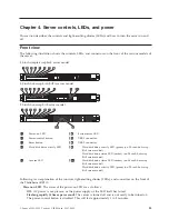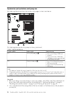
Flashing slowly (once per second):
The server is turned off and is ready to be turned on. You can
press the power-control button to turn on the server.
Lit:
The server is turned on.
Fading on and off:
The server is in a reduced-power state. To wake the server, press the
power-control button or use the IMM Web interface. See “Logging on to the Web interface” on page
109 for information on logging on to the IMM Web interface.
v
Power-control button:
Press this button to turn the server on and off manually or to wake the server
from a reduced-power state.
v
Reset button:
Press this button to reset the server and run the power-on self-test (POST). You might
have to use a pen or the end of a straightened paper clip to press the button.
v
Hard disk drive activity LEDs:
When this LED is flashing, it indicates that the associated hard disk
drive is in use.
v
Locator LED:
Use this blue LED to visually locate the server among other servers. This LED is also
used as a presence detection button. This LED is controlled by the IMM.
v
System-error LED:
When this amber LED is lit, it indicates that a system error has occurred.
v
USB connectors:
Connect a USB device, such as a USB mouse, keyboard, or other device to any of
these connectors.
v
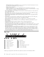
DVD eject button:
Press this button to release a DVD or CD from the DVD drive.
v
DVD drive activity LED:
When this LED is lit, it indicates that the DVD drive is in use.
v
Hot-swap hard disk drive activity LEDs (some models):
Each hot-swap hard disk drive has an activity
LED, and when this LED is flashing, it indicates that the drive is in use. This LED is used on SAS or
SATA hard disk drives.
v
Hot-swap hard disk drive status LEDs (some models):
Each hot-swap hard disk drive has a status
LED. When this LED is lit, it indicates that the drive has failed. If an optional IBM RAID controller is
installed in the server, when this LED is flashing slowly (one flash per second), it indicates that the
drive is being rebuilt. When the LED is flashing rapidly (three flashes per second), it indicates that the
controller is identifying the drive. This LED is used on SAS or SATA hard disk drives.
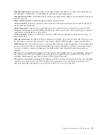
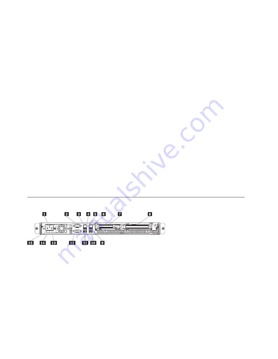
Rear view
1
Power-cord connector
9
NMI button
2
Serial connector
10
USB 3-4 connector
3
Ethernet 1 activity LED
11
USB 1-2 connector
4
Ethernet 1 link LED
12
Video connector
5
Ethernet 2 activity LED
13
Power supply error LED (amber)
6
Ethernet 2 link LED
14
DC power LED (green)
7
PCI slot 1
15
AC power LED (green)
8
PCI slot 2
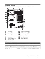
Following is an explanation of the LEDs and connectors on the rear of the ThinkServer RS210:
14
ThinkServer RS210, Types 6531, 6532, 6533, and 6534: Installation and User Guide
Summary of Contents for 653417U
Page 1: ...Installation and User Guide ThinkServer RS210 Machine Types 6531 6532 6533 and 6534 ...
Page 2: ......
Page 3: ...ThinkServer RS210 Types 6531 6532 6533 and 6534 Installation and User Guide ...
Page 8: ...vi ThinkServer RS210 Types 6531 6532 6533 and 6534 Installation and User Guide ...
Page 16: ...xiv ThinkServer RS210 Types 6531 6532 6533 and 6534 Installation and User Guide ...
Page 20: ...4 ThinkServer RS210 Types 6531 6532 6533 and 6534 Installation and User Guide ...
Page 22: ...6 ThinkServer RS210 Types 6531 6532 6533 and 6534 Installation and User Guide ...
Page 40: ...24 ThinkServer RS210 Types 6531 6532 6533 and 6534 Installation and User Guide ...
Page 66: ...50 ThinkServer RS210 Types 6531 6532 6533 and 6534 Installation and User Guide ...
Page 128: ...112 ThinkServer RS210 Types 6531 6532 6533 and 6534 Installation and User Guide ...
Page 160: ...144 ThinkServer RS210 Types 6531 6532 6533 and 6534 Installation and User Guide ...
Page 164: ...148 ThinkServer RS210 Types 6531 6532 6533 and 6534 Installation and User Guide ...
Page 173: ...Chinese Class A warning statement Korean Class A warning statement Appendix B Notices 157 ...
Page 174: ...158 ThinkServer RS210 Types 6531 6532 6533 and 6534 Installation and User Guide ...
Page 179: ......
Page 180: ...Printed in USA ...


