


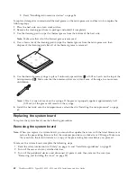
4.
Remove the DIMM air baffle (see “Removing and installing the DIMM air baffle” on page 31).
5.
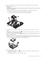
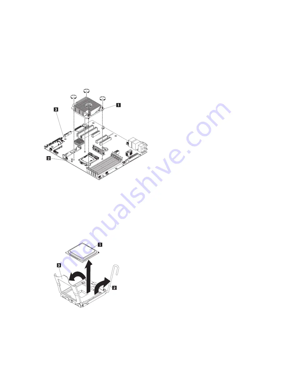
Remove the heat sink.
CAUTION:
The heat sink may become very hot during normal operation. Allow time for the heat sink to cool
down before you touch it.
a.
Loosen the screw on one side of the heat sink to break the seal with the microprocessor.
b.
Press firmly on the captive screws and loosen them with a screwdriver.
c.
Use your fingers to gently pull the heat sink from the microprocessor.
6.
Lift the heat sink out of the server. After removal, place the heat sink on its side on a clean, flat
surface.
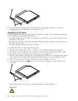
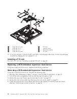
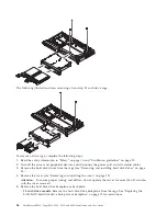
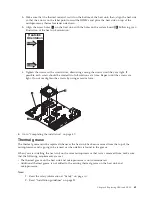
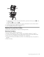
7.
Release the microprocessor retention latch
2
by pressing down on the end, moving it to the side,
and releasing it to the open (up) position.
8.
Open the microprocessor bracket frame
3
by lifting up the tab on the top edge. Keep the bracket
frame in the open position.
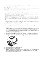
Attention:
Handle the microprocessor carefully. Dropping the microprocessor during removal can
damage the contacts. Also, contaminants on the microprocessor contacts, such as oil from your skin,
can cause connection failures between the contacts and the socket.
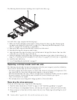
9.
Remove the microprocessor:
a.
Carefully lift the microprocessor
1
straight up and out of the socket, without touching the
microprocessor contacts.
b.
Place the microprocessor on a static-protective surface
Chapter 6. Replacing CRUs and FRUs
59
Summary of Contents for 653417U
Page 1: ...Installation and User Guide ThinkServer RS210 Machine Types 6531 6532 6533 and 6534 ...
Page 2: ......
Page 3: ...ThinkServer RS210 Types 6531 6532 6533 and 6534 Installation and User Guide ...
Page 8: ...vi ThinkServer RS210 Types 6531 6532 6533 and 6534 Installation and User Guide ...
Page 16: ...xiv ThinkServer RS210 Types 6531 6532 6533 and 6534 Installation and User Guide ...
Page 20: ...4 ThinkServer RS210 Types 6531 6532 6533 and 6534 Installation and User Guide ...
Page 22: ...6 ThinkServer RS210 Types 6531 6532 6533 and 6534 Installation and User Guide ...
Page 40: ...24 ThinkServer RS210 Types 6531 6532 6533 and 6534 Installation and User Guide ...
Page 66: ...50 ThinkServer RS210 Types 6531 6532 6533 and 6534 Installation and User Guide ...
Page 128: ...112 ThinkServer RS210 Types 6531 6532 6533 and 6534 Installation and User Guide ...
Page 160: ...144 ThinkServer RS210 Types 6531 6532 6533 and 6534 Installation and User Guide ...
Page 164: ...148 ThinkServer RS210 Types 6531 6532 6533 and 6534 Installation and User Guide ...
Page 173: ...Chinese Class A warning statement Korean Class A warning statement Appendix B Notices 157 ...
Page 174: ...158 ThinkServer RS210 Types 6531 6532 6533 and 6534 Installation and User Guide ...
Page 179: ......
Page 180: ...Printed in USA ...


