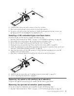

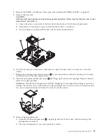
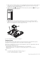
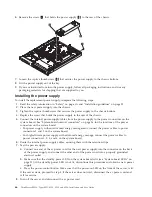
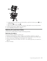
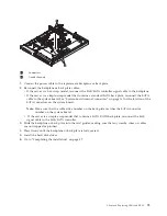
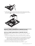
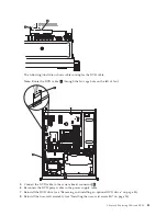
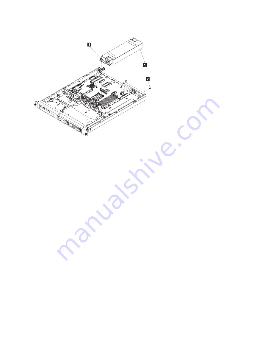
6.
Remove the screw
2
that holds the power supply
1
to the rear of the chassis.
7.
Loosen the captive thumbscrew
3
that secures the power supply to the chassis bottom.
8.
Lift the power supply out of the bay.
9.
If you are instructed to return the power supply, follow all packaging instructions, and use any
packaging materials for shipping that are supplied to you.
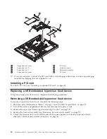
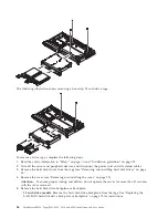
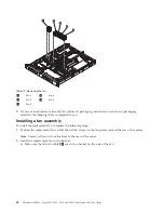
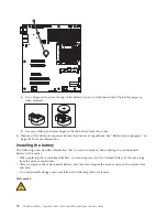
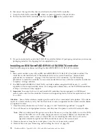
Installing the power supply
To install the replacement power supply, complete the following steps:
1.
Read the safety information in “Safety” on page vii and “Installation guidelines” on page 25.
2.
Place the new power supply into the chassis.
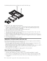
3.
Tighten the captive thumbscrew that secures the power supply to the chassis bottom.
4.
Replace the screw that holds the power supply to the rear of the chassis.
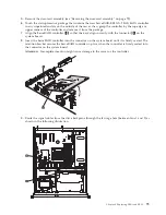
5.
Connect the internal power-supply cables from the power supply to the power connectors on the
system board. See “System-board internal connectors” on page 16 for the locations of the power
connectors on the system board.
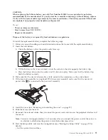
v
For power supply without advanced energy management, connect the power cables to power
connectors 1 and 2 on the system board.
v
For high-efficient power supply with advanced energy manage, connect the power cables to
power connectors 1, 2, 3, and 4 on the system board.
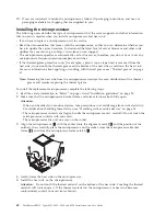
6.
Route the internal power-supply cables, securing them with the retention-clips.
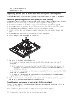
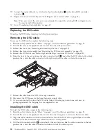
7.
Test the power supply:
a.
Connect one end of the ac power cord for the new power supply into the connector on the back
of the power supply, and connect the other end of the power cord into a properly grounded
electrical outlet.
b.
Make sure that the standby power LED on the system board is lit (see “System-board LEDs” on
page 21); if the standby power LED is not lit, discontinue this procedure and obtain a new power
supply.
c.
Press the power-control button. Make sure that the power-on LED on the front of the server is lit.
If the server starts, proceed to step 8. If the server does not start, disconnect the ac power cord and
call for service.
8.
Turn off the server and disconnect the ac power cord.
66
ThinkServer RS210, Types 6531, 6532, 6533, and 6534: Installation and User Guide
Summary of Contents for 653417U
Page 1: ...Installation and User Guide ThinkServer RS210 Machine Types 6531 6532 6533 and 6534 ...
Page 2: ......
Page 3: ...ThinkServer RS210 Types 6531 6532 6533 and 6534 Installation and User Guide ...
Page 8: ...vi ThinkServer RS210 Types 6531 6532 6533 and 6534 Installation and User Guide ...
Page 16: ...xiv ThinkServer RS210 Types 6531 6532 6533 and 6534 Installation and User Guide ...
Page 20: ...4 ThinkServer RS210 Types 6531 6532 6533 and 6534 Installation and User Guide ...
Page 22: ...6 ThinkServer RS210 Types 6531 6532 6533 and 6534 Installation and User Guide ...
Page 40: ...24 ThinkServer RS210 Types 6531 6532 6533 and 6534 Installation and User Guide ...
Page 66: ...50 ThinkServer RS210 Types 6531 6532 6533 and 6534 Installation and User Guide ...
Page 128: ...112 ThinkServer RS210 Types 6531 6532 6533 and 6534 Installation and User Guide ...
Page 160: ...144 ThinkServer RS210 Types 6531 6532 6533 and 6534 Installation and User Guide ...
Page 164: ...148 ThinkServer RS210 Types 6531 6532 6533 and 6534 Installation and User Guide ...
Page 173: ...Chinese Class A warning statement Korean Class A warning statement Appendix B Notices 157 ...
Page 174: ...158 ThinkServer RS210 Types 6531 6532 6533 and 6534 Installation and User Guide ...
Page 179: ......
Page 180: ...Printed in USA ...


