10.
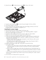
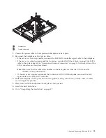
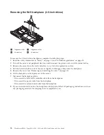
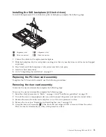
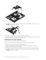
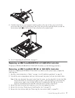
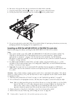
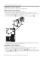
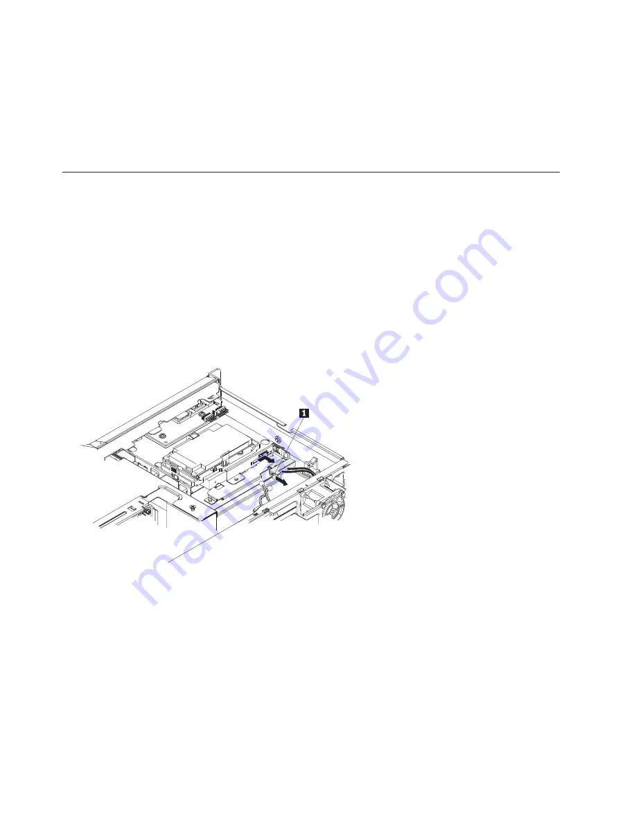
Connect the signal cable that is attached to the drive backplane
1
to the ServeRAID controller
connector
2
.
11.
Replace the riser-card assembly (see “Installing the riser-card assembly” on page 76).
Note:
When you restart the server, you are prompted to import the existing RAID configuration to
the new ServeRAID controller.
12.
Go to “Completing the installation” on page 47.
Replacing the DVD cable
To replace the DVD cable, complete the following procedures:
Removing the DVD cable
To remove the DVD cable, complete the following steps:
1.
Read the safety information in “Safety” on page vii and “Installation guidelines” on page 25.
2.
Turn off the server and peripheral devices and disconnect all power cords.
3.
Remove the cover (see “Removing and installing the cover” on page 29).
4.
Remove the riser-card assembly (see “Replacing the PCI riser-card assembly” on page 75).
5.
Remove the DVD drive (see “Removing and installing an optional DVD drive” on page 45).
6.
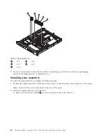
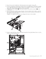
From the front of the server, press the cable connector latch
1
and slide the DVD cable to the unlock
position; then, slide the cable connector to the right and pull the cable out from the connector.
7.
Remove the cable from the DVD drive cage connector.
8.
Disconnect the DVD power cable from the power supply cable.
9.
If you are instructed to return the DVD cable, follow all packaging instructions, and use any
packaging materials for shipping that are supplied to you.
Installing the DVD cable
To install the DVD cable, complete the following steps:
1.
Read the safety information in “Safety” on page vii and “Installation guidelines” on page 25.
2.
Turn off the server and peripheral devices and disconnect the power cords and all external cables.
3.
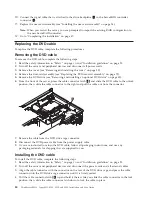
Align the cable connector with the connector on the rear of the DVD drive cage and press the cable
connector into the DVD drive cage connector until it is firmly seated.
4.
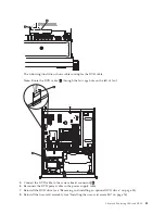
Pull the cable connector latch
2
up and hold it there while you slide the cable connector to the lock
position; then, slide the cable connector latch down to lock the cable in place.
80
ThinkServer RS210, Types 6531, 6532, 6533, and 6534: Installation and User Guide
Summary of Contents for 653417U
Page 1: ...Installation and User Guide ThinkServer RS210 Machine Types 6531 6532 6533 and 6534 ...
Page 2: ......
Page 3: ...ThinkServer RS210 Types 6531 6532 6533 and 6534 Installation and User Guide ...
Page 8: ...vi ThinkServer RS210 Types 6531 6532 6533 and 6534 Installation and User Guide ...
Page 16: ...xiv ThinkServer RS210 Types 6531 6532 6533 and 6534 Installation and User Guide ...
Page 20: ...4 ThinkServer RS210 Types 6531 6532 6533 and 6534 Installation and User Guide ...
Page 22: ...6 ThinkServer RS210 Types 6531 6532 6533 and 6534 Installation and User Guide ...
Page 40: ...24 ThinkServer RS210 Types 6531 6532 6533 and 6534 Installation and User Guide ...
Page 66: ...50 ThinkServer RS210 Types 6531 6532 6533 and 6534 Installation and User Guide ...
Page 128: ...112 ThinkServer RS210 Types 6531 6532 6533 and 6534 Installation and User Guide ...
Page 160: ...144 ThinkServer RS210 Types 6531 6532 6533 and 6534 Installation and User Guide ...
Page 164: ...148 ThinkServer RS210 Types 6531 6532 6533 and 6534 Installation and User Guide ...
Page 173: ...Chinese Class A warning statement Korean Class A warning statement Appendix B Notices 157 ...
Page 174: ...158 ThinkServer RS210 Types 6531 6532 6533 and 6534 Installation and User Guide ...
Page 179: ......
Page 180: ...Printed in USA ...

