background image

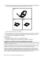
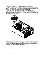
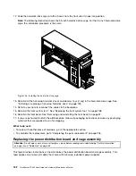
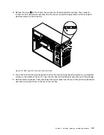
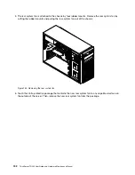
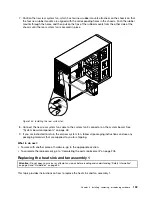
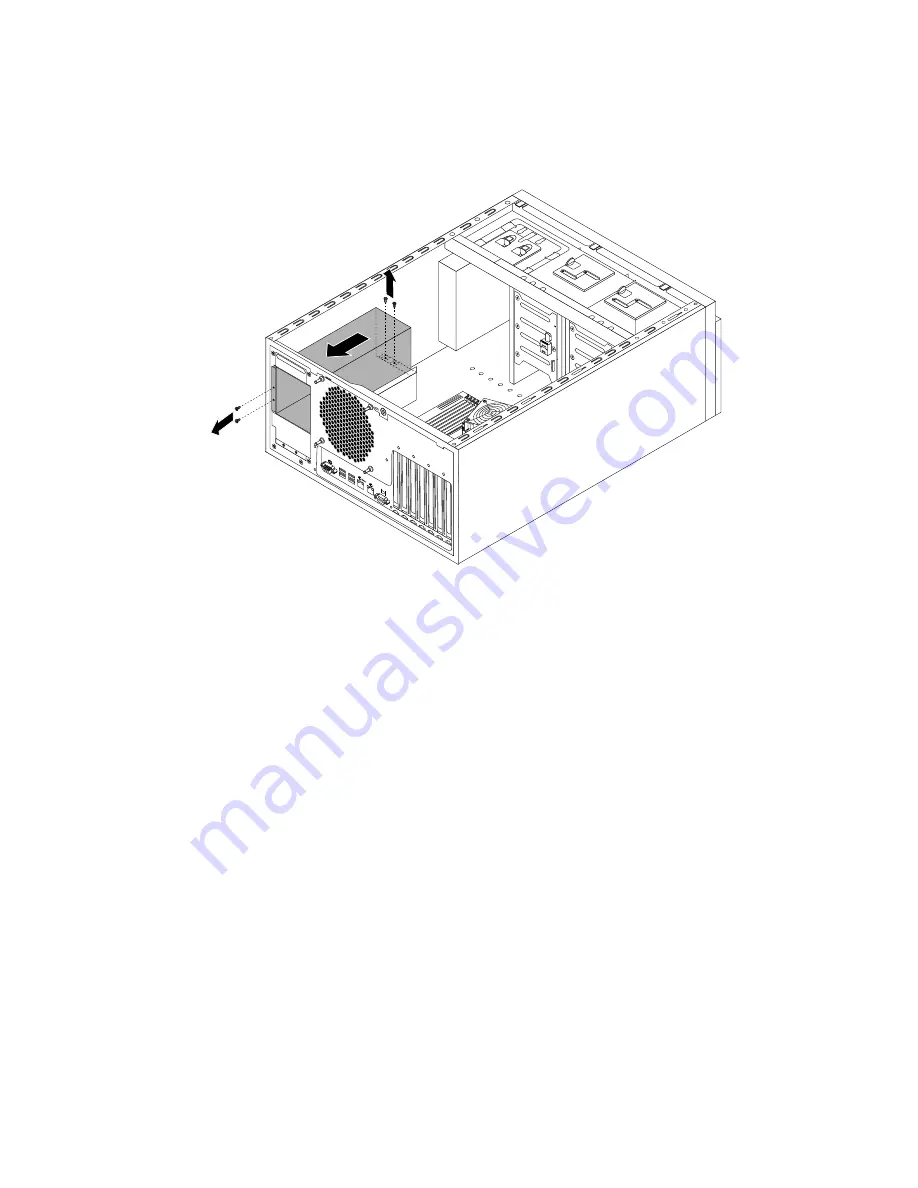
8. Remove the two screws at the rear of the chassis and the two screws on the metal clip at the front of

the power distribution board and cage assembly. Then, push the power distribution board and cage
assembly to the rear, and then carefully slide it out of the chassis.

Figure 127. Removing the power distribution board and cage assembly

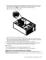
9. Touch the static-protective package that contains the new power distribution board and cage assembly

to any unpainted surface on the outside of the server. Then, remove the new power distribution board
and cage assembly from the package.

184

ThinkServer TD340 User Guide and Hardware Maintenance Manual

Summary of Contents for 70B4

Page 1: ...ThinkServer TD340 User Guide and Hardware Maintenance Manual Machine Types 70B4 70B5 70B6 and 70B7 ...

Page 2: ... your product Safety information on page iii Appendix A Notices on page 219 Third Edition May 2014 Copyright Lenovo 2014 LIMITED AND RESTRICTED RIGHTS NOTICE If data or software is delivered pursuant a General Services Administration GSA contract use reproduction or disclosure is subject to restrictions set forth in Contract No GS 35F 05925 ...

Page 3: ... the system date and time 64 Using passwords 65 Selecting a startup device 66 Configuring the TPM function 66 Exiting the Setup Utility program 67 Updating or recovering the BIOS 67 Using the ThinkServer EasyStartup program 69 Features of the ThinkServer EasyStartup program 69 Starting the ThinkServer EasyStartup program 69 Using the ThinkServer EasyStartup program on a Windows operating system 71...

Page 4: ...cing the system board 198 Completing the parts replacement 205 Reinstalling the server cover and reconnecting cables 205 Updating the server configuration 207 Chapter 7 Troubleshooting and diagnostics 209 Troubleshooting procedure 209 Viewing the status and diagnostic LEDs 209 Using a diagnostic program 209 Viewing the system event log 210 Basic troubleshooting tables 210 ThinkServer EasyStartup p...

Page 5: ...teen käyttöä Avant d utiliser le produit veillez à bien lire et comprendre les instructions de sécurité multilingues figurant sur le DVD de documentation fourni avec le produit Πριν χρησιμοποιήσετε το προϊόν βεβαιωθείτε ότι έχετε διαβάσει και κατανοήσει τις οδηγίες ασφάλειας οι οποίες είναι διαθέσιμες σε διάφορες γλώσσες στο DVD τεκμηρίωσης που συνοδεύει το προϊόν Vor Verwendung des Produkts sollt...

Page 6: ... s produktom Preden začnete uporabljati izdelek je pomembno da preberete in razumete večjezična varnostna navodila na DVD ju z dokumentacijo ki ste ga prejeli skupaj z izdelkom Antes de utilizar el producto asegúrese de leer y comprender las instrucciones de seguridad multilingües del DVD de documentación que se proporciona con el producto Var noga med att läsa säkerhetsinstruktionerna på dokument...

Page 7: ...ess instructed otherwise in the installation and configuration procedures Connect and disconnect cables as described in the following table when installing moving or opening covers on this product or attached devices To connect To disconnect 1 Turn everything OFF 2 First attach all cables to devices 3 Attach signal cables to connectors 4 Attach power cords to outlets 5 Turn devices ON 1 Turn every...

Page 8: ...ss 3B laser diode Note the following Laser radiation when open Do not stare into the beam do not view directly with optical instruments and avoid direct exposure to the beam Statement 4 18 kg 39 7 lb 32 kg 70 5 lb 55 kg 121 2 lb 32 kg 70 5 lb 55 kg 121 2 lb 100 kg 220 5 lb CAUTION Use safe practices when lifting Statement 5 CAUTION The power control button on the device and the power switch on the...

Page 9: ...oors will not support the weight of the device Statement 8 CAUTION Never remove the cover on a power supply or any part that has the following label attached Hazardous voltage current and energy levels are present inside any component that has this label attached There are no serviceable parts inside these components If you suspect a problem with one of these parts contact a service technician Sta...

Page 10: ...ded on the rails Statement 14 CAUTION Some accessory or option board outputs exceed Class 2 or limited power source limits You must install the appropriate interconnecting cabling in accordance with your local electrical code requirements Statement 15 CAUTION The power control button on the device may put the device in standby mode instead of turning off the device In addition the device might hav...

Page 11: ... 60 V direct current The branch circuit overcurrent protection must be rated in accordance with local electrical code requirements Use 1 3 mm2 or 16 American Wire Gauge AWG copper conductor only not exceeding 3 meters in length Torque the wiring terminal screws to 1 4 newton meters or 12 inch pounds Provide a readily available approved and rated disconnect device in the field wiring Statement 17 C...

Page 12: ... by local regulations Products that are not assessed Typical products that are not assessed include but not limited to the following Server and IT rack components for example uninterruptible power supplies and current distribution systems Devices in IT rooms for example bulk storage units and network products Industrial low voltage switchgear x ThinkServer TD340 User Guide and Hardware Maintenance...

Page 13: ...n DVD that comes with your server A printable generic version of the latest LLW also is available in more than 30 languages at http www lenovo com warranty llw_02 If you cannot obtain the LLW through the documentation DVD or Lenovo Web site contact your local Lenovo office or reseller to obtain a printed version of the LLW free of charge For warranty service consult the worldwide Lenovo Support te...

Page 14: ...ious documentation for your server and instructions on how to obtain all the documentation Printed document The following document is printed out and contained in your server package Read Me First This is a multilingual document you should read first This document provides instructions on how to access the complete safety warranty and support information on the documentation DVD that comes with yo...

Page 15: ...elp you use configure and maintain your server ThinkServer Management Module User Guide This document provides information about server remote management This document is in English only You might find this document on the documentation DVD that comes with your server If not download it from the Lenovo Web site at http www lenovo com UserManuals Note To obtain advanced remote management functions ...

Page 16: ...4 ThinkServer TD340 User Guide and Hardware Maintenance Manual ...

Page 17: ... cords to the server See Rear view of the server on page 21 to locate the connectors 4 Turn on the server to verify operation See Turning on the server on page 59 5 Review the Unified Extensible Firmware Interface UEFI Basic Input Output System BIOS settings and customize as needed See Using the Setup Utility program on page 61 6 Configure RAID and install the operating system and basic drivers Se...

Page 18: ...6 ThinkServer TD340 User Guide and Hardware Maintenance Manual ...

Page 19: ...tion DVD and software media Note Depending on the model your server might look slightly different from the following illustration Figure 1 Server package 1 Server 2 Material box including power cords printed documentation a documentation DVD and software media Features This topic provides general information about the server features for various models Depending on your specific model some feature...

Page 20: ...drives Internal drives are devices that your server uses to read and store data The internal drives supported by your server vary by model Hard disk drive Your server supports one of the following hard disk drive configurations Up to four 3 5 inch hot swap Serial Advanced Technology Attachment SATA or Serial Attached SCSI SAS hard disk drives SCSI is the acronym for Small Computer System Interface...

Page 21: ...store data on tapes To connect an external tape drive see Connecting an external tape drive on page 162 Expansion slots The server has six expansion slots on the system board for installing appropriate Peripheral Component Interconnect PCI cards or PCI Express cards For detailed information see System board components on page 48 Input Output I O features One serial connector on the rear panel One ...

Page 22: ... condition the server operating system is in and no matter if the server is on or off as long as the server is connected to network and an ac power source the interaction with the TMM controlled servers can be achieved through system network The user can obtain the server hardware health information and system event log SEL and is able to conduct the operations including turning on or off the serv...

Page 23: ...etwork LAN a network administrator can remotely turn on or wake up the computer from a management console using remote network management software Besides many other functions such as data transfer and software updates can be performed remotely without remote attendance and can be done after normal working hours and on weekends to save time and increase productivity Advanced system management feat...

Page 24: ...tware programs that you can use to help you set up use and maintain the server ThinkServer EasyStartup The ThinkServer EasyStartup program simplifies the process of configuring RAID and installing supported Microsoft Windows and Linux operating systems and device drivers on your server This program is provided with your server on a self starting bootable ThinkServer EasyStartup DVD The user guide ...

Page 25: ...tware The integrated TMM provides basic remote management features for the server The add on TMM Premium option provides advanced remote management features for the server For detailed information about the remote management software and server remote management refer to the ThinkServer Management Module User Guide which is available for download at http www lenovo com UserManuals Diagnostic progr...

Page 26: ... model and serial number labels on the server Note Depending on the model type your server might look slightly different from this illustration Figure 2 Machine type model and serial number labels 14 ThinkServer TD340 User Guide and Hardware Maintenance Manual ...

Page 27: ...s 7 Front door lock 3 Optical drive bay 1 with an optical drive installed 8 Front door handle 4 Optical drive eject close button 9 Intelligent diagnostics module panel available in some models 5 Optical drive status LED 1 Front panel For detailed information about the control connectors and status LEDs on the front panel see Front panel on page 17 2 Optical drive bay 2 The 5 25 inch optical drive ...

Page 28: ...l drive is working or in the POST process 6 Front door 7 Front door lock You can lock the front door to protect the hard disk drive cages from unauthorized access 8 Front door handle Use the front door handle to open the front door 9 Intelligent diagnostics module panel The intelligent diagnostics module panel is only available in models that come with an intelligent diagnostics module For more in...

Page 29: ...tus LED 5 System status LED 2 Hard disk drive status LED 6 Front USB connector 1 3 Network Interface Controller NIC 1 status LED 7 Front USB connector 2 4 NIC 2 status LED 1 Power switch with power status LED Press the power switch to turn on the server when you finish setting up the server Hold the power switch for several seconds to turn off the server if you cannot turn it off from the operatin...

Page 30: ...r Description On Green The server is connected to a LAN Off None The server is disconnected from a LAN Blinking Green The LAN is connected and active 5 System error LED The system error LED helps you to determine if there are any system errors Off The server is off or the server is on and working correctly Amber The server has potential system errors Check the information in the following table fo...

Page 31: ...he BMC for errors and then check the system fans 6 Front USB connector 1 7 Front USB connector 2 Used to attach a USB compatible device such as a USB keyboard mouse scanner or printer If you have more than six USB devices you can purchase a USB hub which you can use to connect additional USB devices Intelligent diagnostics module This topic provides information about the intelligent diagnostics mo...

Page 32: ...ure 1 Microprocessor status LED also known as CPU error LED Solid on amber One or more microprocessors are overheated Check the BMC for errors and run the diagnostic programs See Using a diagnostic program on page 209 Solid off The memory modules are operating at a normal temperature 2 Memory module status LED Solid on amber One or more memory modules are overheated Check the BMC for errors and ru...

Page 33: ...id on amber The ambient temperature is below 7 C 44 6 F or over 40 C 104 F Check the BMC for errors and run the diagnostic programs See Using a diagnostic program on page 209 Solid off The power supply is working correctly 5 Power supply error LED Solid on amber The power supply is likely to fail or has failed Check the BMC for errors and run the diagnostic programs See Using a diagnostic program ...

Page 34: ... from the illustrations in this topic Figure 6 Rear view of the server with a non hot swap power supply assembly 1 Power cord connector 6 VGA DB 15 connector 2 Serial connector 7 ID LED 3 USB connectors 4 8 Expansion card area 4 Ethernet connector 1 for system management RJ 45 9 Front door key 5 Ethernet connector 2 RJ 45 22 ThinkServer TD340 User Guide and Hardware Maintenance Manual ...

Page 35: ...rking correctly When the LED is lit in amber it indicates that the hot swap redundant power supply is likely to fail or has failed Figure 7 Rear view of the server with hot swap redundant power supplies 1 Power cord connectors Used to connect the power cords 2 Serial connector Used to attach a device that uses a 9 pin serial connector 3 USB connectors Used to attach a USB compatible device such as...

Page 36: ... and active Amber On The connection speed is 1000 Mbps Green On The connection speed is 100 Mbps 2 Left None Off The connection speed is 10 Mbps 6 VGA DB 15 connector Used to attach a VGA compatible video device such as a VGA monitor 7 ID LED When you press the ID button the ID LED on the rear of the server is lit to help you locate the server among other servers You also can turn on the ID LED us...

Page 37: ...r guide is available for download at http www lenovo com UserManuals Table 1 ThinkServer Host Bus Adapter specification Physical link width Negotiable link width Type x8 x8 x4 x2 x1 Low profile card If the server does not have a RAID card or a VGA adapter card installed the Host Bus Adapter also can be installed in the PCI Express x16 card slot PCI E slot 5 on the system board See System board com...

Page 38: ...Padlock Your server comes with a padlock loop When a padlock is installed the server cover cannot be removed Figure 9 Padlock 26 ThinkServer TD340 User Guide and Hardware Maintenance Manual ...

Page 39: ...aches to the integrated cable lock slot at the rear of your server and is operated with a key The cable lock also locks the server cover This is the same type of lock used with many notebook computers You can order an integrated cable lock from Lenovo by searching for Kensington at http www lenovo com support Figure 10 Integrated cable lock Chapter 3 Product overview 27 ...

Page 40: ...ge 13 To remove the server cover and access the inside of the server see Removing the server cover on page 85 The chassis configuration varies by model The following illustrations show the three main chassis configurations based on the supported hard disk drives Server models with up to eight 3 5 inch hot swap SATA or SAS hard disk drives Server models with up to sixteen 2 5 inch hot swap SAS hard...

Page 41: ...ard disk drives 1 Heat sink and fan assembly 2 14 Hard disk drive bay 1 2 CPU1 DIMMs vary by model 15 Hard disk drive bay 0 3 Heat sink and fan assembly 1 16 Front system fan 1 4 Intelligent Diagnostics Module available in some models 17 Front system fan 2 5 Front panel 18 System board 6 Optical drive bay 2 with an optical drive installed in some models 19 System board battery 7 Optical drive bay ...

Page 42: ...o sixteen 2 5 inch hot swap SAS hard disk drives Figure 13 Components of server models with up to sixteen 2 5 inch hot swap SAS hard disk drives 1 Heat sink and fan assembly 2 18 Hard disk drive bay 5 2 CPU1 DIMMs vary by model 19 Hard disk drive bay 4 3 Heat sink and fan assembly 1 20 Hard disk drive bay 3 4 Intelligent Diagnostics Module available in some models 21 Hard disk drive bay 2 5 Front ...

Page 43: ... CPU2 DIMMs vary by model 17 Hard disk drive bay 6 Notes The low profile PCI card bracket 28 and main PCI card bracket 29 are available in server models that come with a RAID card If your server has up to eight 2 5 inch hot swap SAS hard disk drives the hot swap SAS hard disk drives need to be installed into the hard disk drive bays 0 1 2 3 4 5 6 and 7 The following illustration shows the componen...

Page 44: ... or request that a technician install the optional service CRU under the terms of the applicable warranty service type for your country or region Non CRUs must be replaced only by trained service technicians The following table lists the major FRUs in your server and the CRU identification information For a complete listing of FRU information such as FRU part numbers and supported server models go...

Page 45: ...d RAID available as an option Yes No ThinkServer RAID 500 Upgrade Key for Advanced RAID available as an option Yes No ThinkServer RAID 700 Battery available as an option No Yes ThinkServer Trusted Platform Module available as an option Yes No Hot swap hard disk drive status LEDs This topic applies only to server models with hot swap hard disk drives Note Depending on the model your server might lo...

Page 46: ...Figure 15 3 5 inch hot swap hard disk drive status LEDs 34 ThinkServer TD340 User Guide and Hardware Maintenance Manual ...

Page 47: ...rive is active and data is being transferred On green Blinking rapidly about four flashes per second amber The RAID controller is identifying the hard disk drive On green On amber The RAID array has failed and cannot be recovered You need to recreate a new array Blinking green Blinking slowly about one flash per second amber The hard disk drive is being rebuilt RAID card This topic provides inform...

Page 48: ...also known as ThinkServer 9240 8i RAID 0 1 Adapter ThinkServer RAID 700 Adapter also known as ThinkServer 9260 8i SAS RAID Adapter ThinkServer RAID 710 Adapter also known as 9270CV 8i RAID adapter ThinkServer RAID 500 Adapter also known as ThinkServer 9240 8i RAID 0 1 Adapter The following illustration shows the connectors on the ThinkServer RAID 500 Adapter Figure 17 ThinkServer RAID 500 Adapter ...

Page 49: ...onnector 2 Ports 3 0 4 ThinkServer RAID 700 Battery connector 1 Ports 7 4 Used to connect a mini SAS signal cable See Connecting the cables on page 43 2 Ports 3 0 Used to connect a mini SAS signal cable See Connecting the cables on page 43 3 External connector Used to attach the cable that connects a RAID card to the system board hard disk drive LED connector See Connecting the cables on page 43 4...

Page 50: ...pander card This topic provides information to help you locate the connectors on the expander card if your server has one installed in the shorter slot of the riser card assembly 1 The expander card works together with the RAID card by expanding the ports on the RAID card so that the server can support up to 16 hard disk drives Note The server must have a RAID card and an expander card installed t...

Page 51: ...tor 6 Hot swap hard disk drive backplane Your server comes with one of the following hot swap hard disk drive and backplane configurations Up to four 3 5 inch hot swap SATA or SAS hard disk drives with one backplane Five to eight 3 5 inch hot swap SATA or SAS hard disk drives with two backplanes Up to eight 2 5 inch hot swap SAS hard disk drives or SATA solid state drives with one backplane Nine t...

Page 52: ...g on the model your server might look slightly different from the following illustration 2 The following illustration is based on server models that have five to eight 3 5 inch hot swap SATA or SAS hard disk drives with two backplanes 1 Figure 21 Backplane locations 3 5 inch hot swap hard disk drive backplane This topic provides information to help you locate the connectors on a 3 5 inch hot swap ...

Page 53: ...rive Figure 23 Rear view of the 3 5 inch hot swap hard disk drive backplane 1 8 pin power connector For the 3 5 inch hot swap hard disk drive backplane on the lower hard disk drive cage connect the P5 power connector of the power supply to the 8 pin power connector on the backplane For the 3 5 inch hot swap hard disk drive backplane on the upper hard disk drive cage connect the P4 power connector ...

Page 54: ... Slot 4 for a 2 5 inch SAS hot swap hard disk drive 2 Slot 1 for a 2 5 inch SAS hot swap hard disk drive 6 Slot 5 for a 2 5 inch SAS hot swap hard disk drive 3 Slot 2 for a 2 5 inch SAS hot swap hard disk drive 7 Slot 6 for a 2 5 inch SAS hot swap hard disk drive 4 Slot 3 for a 2 5 inch SAS hot swap hard disk drive 8 Slot 7 for a 2 5 inch SAS hot swap hard disk drive Figure 25 Rear view of the 2 5...

Page 55: ...bles from the system board to the non hot swap hard disk drives on page 47 Connecting the mini SAS signal cables from the system board to the hot swap hard disk drive backplanes To connect the mini SAS signal cables from the system board to the backplanes do the following 1 Use one mini SAS to mini SAS signal cable Connect one connector of the mini SAS signal cable to the SAS connector 0 3 on the ...

Page 56: ...ons Note The option package for the RAID card is designed for different types of servers and might contain additional cables that are not required for installation To connect the mini SAS signal cables from the RAID card to the backplanes do the following If you are using a ThinkServer RAID 500 Adapter do the following 1 Use one mini SAS to mini SAS signal cable Connect the mini SAS connector 1 on...

Page 57: ... of the cable to the mini SAS signal cable connector 1 on the 2 5 inch hot swap hard disk drive backplane or to the mini SAS signal cable connector 0 on the 3 5 inch hot swap hard disk drive backplane The 3 5 inch hot swap hard disk drive backplane is installed on the upper hard disk drive cage Figure 27 Connecting the mini SAS signal cables from the RAID card to the backplanes For the connector l...

Page 58: ...r RAID 700 Adapter Then connect the mini SAS connector on the other end of the cable to the connector 2 on the expander card If you are using a ThinkServer RAID 710 Adapter do the following 1 Use a mini SAS to mini SAS signal cable and connect the mini SAS connector on one end of the cable to the port 1 on the ThinkServer RAID 710 Adapter Then connect the mini SAS connector on the other end of the...

Page 59: ...e cable to the mini SAS connector 0 on the backplane installed on the upper hard disk drive cage 4 For hard disk drive 12 to hard disk drive 15 use a mini SAS to mini SAS signal cable and connect the mini SAS connector 4 on one end of the cable to the connector 6 on the expander card Then connect the mini SAS connector on the other end of the cable to the mini SAS connector 1 on the backplane inst...

Page 60: ...stalled in bay 2 P7 power connector SATA connector 2 Installed in bay 3 P8 power connector SATA connector 3 System board components The following illustration shows the component locations on the system board Figure 29 System board components 1 System fan 3 connector 21 SATA connector 4 2 Microprocessor socket 2 22 SAS connector 4 7 3 Microprocessor 2 fan connector 23 SAS connector 0 3 4 Microproc...

Page 61: ...rocessor socket 2 8 Microprocessor socket 1 If the server has two microprocessors each of the microprocessor is secured in the microprocessor socket on the system board and a heat sink and fan assembly is installed above the microprocessor to provide cooling If the server has only one microprocessor the microprocessor socket 2 is protected by a microprocessor socket cover 3 Microprocessor 2 fan co...

Page 62: ...er features including the onboard SATA SAS software RAID 13 iButton socket By default your server supports onboard SATA SAS software RAID levels 0 1 and 10 However you can activate onboard SATA SAS software RAID 5 by installing a ThinkServer RAID 100 or RAID 300 upgrade key for Advanced RAID in the iButton socket For more information see Installing or removing the ThinkServer RAID 100 or RAID 300 ...

Page 63: ...s Module connector Used to connect the cable of the Intelligent Diagnostics Module 28 Front panel connector Used to connect the front panel cable 29 Internal USB connector 5 6 30 Internal USB connector 7 8 Used to connect the front panel USB cables 31 System board battery Your server has a special type of memory that maintains the date time and configuration information for built in features The s...

Page 64: ...xpress x16 card with 167 mm 6 57 inches in length such as a RAID card 39 PCI Express x8 card slot PCI E slot 6 This PCI card slot supports a PCI Express x8 card with 167 mm 6 57 inches in length such as an Ethernet card System board jumpers and switches This topic provides information about the jumpers and switches on the system board A jumper is a short length of conductor used to set up or adjus...

Page 65: ...y information on page iii and Guidelines on page 83 1 ThinkServer Management Module Enable Disable jumper When the ThinkServer Management Module Enable Disable jumper hereinafter referred to as the TMM Enable Disable jumper is in the default normal position pin 1 and pin 2 the server needs about 30 seconds for the TMM to initialize whenever you connect the server to an ac power source If you press...

Page 66: ... with the server 3 Remove the server cover See Removing the server cover on page 85 4 Locate the Clear CMOS jumper on the system board Then remove any parts and disconnect any cables that might impede your access to the jumper 5 Move the clear CMOS jumper from the default normal position pin 1 and pin 2 to the short circuited position pin 2 and pin 3 6 Wait more than five seconds and then move the...

Page 67: ...d while the BIOS is being updated and your server cannot start correctly To recover the BIOS see Recovering from a BIOS update failure on page 68 2 Clear password switch Used to erase forgotten passwords such as an administrator password and a user password To clear passwords do the following 1 Remove all media from the drives and turn off all attached devices and the server Then disconnect all po...

Page 68: ...ectrical outlets and disconnect all cables that are connected to the server 2 If the server is installed in a rack cabinet remove the server from the rack cabinet and place it on a flat clean and static protective surface See the Rack Installation Instructions that comes with the server 3 Remove the server cover See Removing the server cover on page 85 4 Locate the ME in force update switch on the...

Page 69: ...ror LED on the system board is lit it indicates that the corresponding system fan is operating too slowly or has failed To solve the problem you might need to reinstall or replace the system fan See Replacing the front system fan 1 on page 188 or Replacing the rear system fan on page 190 If it is a system board problem contact the Lenovo Customer Support Center 4 5 Microprocessor fan error LEDs Wh...

Page 70: ...er Management Module TMM status of your server ThinkServer Management Module status LED Color Description On Green The TMM is not ready Off None The TMM has no power or has failed Blinking Green The TMM is working 58 ThinkServer TD340 User Guide and Hardware Maintenance Manual ...

Page 71: ...wer supply do not turn off the electrical current supplied to the device The device also might have more than one power cord To remove all electrical current from the device ensure that all power cords are disconnected from the power source The server can be turned off in one of the following ways Turn off the server from the operating system if your operating system supports this feature After an...

Page 72: ...source the server also can respond to a remote request to turn on the server To remove all power from the server you must disconnect the server from the ac power source 2 For information about your specific operating system refer to the related documentation or help system for the operating system 60 ThinkServer TD340 User Guide and Hardware Maintenance Manual ...

Page 73: ...en wait for several seconds and the Setup Utility program opens If you have set a password you need to type the correct password to enter the Setup Utility program For password information see Using passwords on page 65 Viewing information in the Setup Utility program The Setup Utility program menu lists various items about the system configuration Select a desired item to view information or chan...

Page 74: ...ists of the following menus Main menu on page 62 Advanced menu on page 62 Security menu on page 63 Server Management menu on page 63 Boot Options menu on page 64 Boot Manager menu on page 64 Save Exit menu on page 64 Lenovo provides the BIOS update utility on the Lenovo Support Web site You can download the BIOS update utility to update the BIOS if the newer BIOS version specifically solves a prob...

Page 75: ...gram For each menu item press Enter to show selectable options and select a desired option by using the up and down arrow keys or type desired values from the keyboard Some items are displayed on the menu only if the server supports the corresponding features Notes Enabled means that the function is configured Disabled means that the function is not configured The Security menu contains the follow...

Page 76: ...selection window See Selecting a startup device on page 66 Save Exit menu After you finish viewing or changing settings in the Setup Utility program you can choose a desired action from the Save Exit menu to save changes discard changes or load default values and exit the program Press Enter to select the item on the Save Exit menu and then select Yes when prompted to confirm the action For inform...

Page 77: ...th the administrator password and user password are set you can type either password to use the server However you must use your administrator password to change any configuration settings Password considerations For security reasons it is recommended to use a strong password that cannot be easily compromised Notes The Setup Utility program passwords are not case sensitive The server supports Setu...

Page 78: ...nu The boot device selection window opens 3 In the boot device selection window use the up and down arrow keys on the keyboard to switch between the selections Press Enter to select the device of your choice Then the server will start up from the selected device To view or permanently change the configured startup device sequence do the following 1 Start the Setup Utility program See Starting the ...

Page 79: ...TMM firmware provides remote management features Lenovo might make changes and enhancements to the BIOS and TMM firmware When updates are released they are available for download on the Lenovo Web site at http www lenovo com drivers You can update the server firmware by downloading an update package and following the instructions on the Web page You also can use the Firmware Updater program to hel...

Page 80: ... put the amiboot rom file contained in the package into the root directory of a bootable USB key 2 Remove all media from the drives and turn off all attached devices and the server Then disconnect all power cords from electrical outlets and disconnect all cables that are connected to the server 3 Remove the server cover See Removing the server cover on page 85 4 Locate the BIOS recovery switch on ...

Page 81: ...EasyStartup program 3 Print the readme file and read it carefully 4 Use an optical drive and any DVD burning software to create a bootable disc with the ISO image Features of the ThinkServer EasyStartup program This topic lists the features of the ThinkServer EasyStartup program The ThinkServer EasyStartup program has the following features Contained in a self starting bootable DVD Easy to use lan...

Page 82: ...he screen and select a desired option Then follow the instructions on the screen If this is the first time you are using the ThinkServer EasyStartup program select the option to continue to the main interface and view the compatibility notes and user guide Notes Functionality and supported operating systems vary depending on the version of the ThinkServer EasyStartup program From the main interfac...

Page 83: ...e root directory of the DVD Notes To use the program read and accept the Lenovo License Agreement when prompted You might need to add the Uniform Resource Locator URL for the ThinkServer EasyStartup program Web page to the trusted Web site list so that the page can open correctly You can do the following when using the ThinkServer EasyStartup program on a Windows operating system For detailed info...

Page 84: ... prevented by reconstructing missing data from the remaining drives The following list describes some of the most commonly used RAID levels RAID 0 block level striping without parity or mirroring Simple stripe sets are normally referred to as RAID 0 RAID 0 uses striping to provide high data throughput especially for large files in an environment that does not require fault tolerance RAID 0 has no ...

Page 85: ...is a spanned drive group in which data is striped across multiple RAID 5 drive groups RAID 50 works best with data that requires high reliability high request rates high data transfers and medium to large capacity Note Having virtual drives of different RAID levels such as RAID 0 and RAID 5 in the same drive group is not allowed For example if an existing RAID 5 virtual drive is created out of par...

Page 86: ...ty of the primary RAID array is limited to 2 TB RAID array status When you turn on the server the RAID controller ROM version the RAID array status and the list of available hard disk drives will be displayed during the POST The RAID array status can be one of the following Online This is the normal status which indicates that the RAID array is working correctly Degrade This status indicates that ...

Page 87: ...the event of a physical drive failure You can choose to rebuild the data on the failing drive if the drive is still operational If the drive is not operational it must be replaced and the data on the failing drive must be rebuilt on a new drive to restore the system to fault tolerance If hot spare drives are available the failing drive might be rebuilt automatically without any user intervention C...

Page 88: ...lowing 1 Start the LSI Software RAID Configuration Utility program See Starting the LSI Software RAID Configuration Utility program on page 74 2 On the main interface of the program do one of the following depending on your needs If you want to create a RAID array select Easy Configuration and then follow the instructions on the screen If you want to add a secondary RAID array if supported by your...

Page 89: ...re drives refer to Introduction to RAID in the MegaRAID SAS Software User Guide on the documentation DVD that comes with your server To set a hard disk drive as a hot spare drive using the LSI Software RAID Configuration Utility program do the following 1 Start the LSI Software RAID Configuration Utility program See Starting the LSI Software RAID Configuration Utility program on page 74 2 Do one o...

Page 90: ...nsistency check This topic provides instructions on how to run a consistency check for virtual drives using the LSI Software RAID Configuration Utility program The consistency check operation verifies that all stripes on a virtual drive with a redundant RAID level RAID 1 RAID 5 and RAID 10 are consistent and the date on the virtual drive is correct For example in a system with parity checking cons...

Page 91: ...stem Events and Storage Devices Maintaining and Managing Storage Configurations The MegaRAID SAS Software User Guide also is available on the Lenovo Web site at http www lenovo com UserManuals Configuring the advanced SATA SAS hardware RAID Before configuring RAID for your server observe the following precautions Use hard disk drives that are of the same type SATA or SAS and have the same capacity...

Page 92: ...test level of firmware such as the BIOS updates and device drivers When you replace a device in the server you might have to either update the server with the latest version of the firmware that is stored in memory on the device or reflash the BIOS the TMM firmware and the FRU SDR Using the Firmware Updater program The Firmware Updater program enables you to maintain your system firmware up to dat...

Page 93: ...ge program go to http www lenovo com drivers and follow the instructions on the Web page For detailed information about using the Lenovo ThinkServer EasyManage program refer to the help system for the program Chapter 5 Configuring the server 81 ...

Page 94: ...82 ThinkServer TD340 User Guide and Hardware Maintenance Manual ...

Page 95: ...nd that your server is ready to function at maximum levels of performance To download firmware updates for your server go to http www lenovo com drivers and follow the instructions on the Web page See Updating the firmware on page 80 for more information Before you install optional hardware devices ensure that the server is working correctly If the server is not working correctly see Chapter 7 Tro...

Page 96: ...ly effective When you handle server parts and components take these precautions to avoid static electricity damage Limit your movement Movement can cause static electricity to build up around you Always carefully handle the parts and other components such as PCI Express cards memory modules system boards and microprocessors by edges or frame Do not touch solder joints pins or exposed circuitry Do ...

Page 97: ...ours When replacing a hot swap drive install the new hot swap drive within two minutes of removal If your server has air ducts or air baffles do not remove them while the server is running Operating the server without the air ducts or air baffles might cause the microprocessors to overheat For servers that support up to two microprocessors ensure that the second microprocessor socket always contai...

Page 98: ...are connected to the server 4 Remove any locking device that secures the server cover such as a padlock or an integrated cable lock See Server locks on page 25 5 Loosen the thumbscrew that secures the server cover and then slide the server cover to the rear until it is stopped Notes a The server cover is securely installed and you need to use a tool such as a screwdriver to loosen the thumbscrew t...

Page 99: ...mation on page iii and Guidelines on page 83 This topic provides instructions on how to remove and reinstall the front bezel Before you begin print all the related instructions or ensure that you can view the PDF version on another computer for reference Note Depending on the model your server might look slightly different from the illustrations in this topic To remove and reinstall the front beze...

Page 100: ...ve the front bezel by releasing the three plastic tabs on the left side and pivoting the front bezel outward Figure 36 Removing the front bezel 88 ThinkServer TD340 User Guide and Hardware Maintenance Manual ...

Page 101: ...to remove and reinstall the PCI card bracket assembly This topic applies only to server models that have a RAID card installed Before you begin print all the related instructions or ensure that you can view the PDF version on another computer for reference To remove and reinstall the PCI card bracket assembly do the following 1 Remove all media from the drives and turn off all attached devices and...

Page 102: ...es in the PCI card bracket assembly Figure 38 Releasing the PCI card bracket assembly b Carefully move the PCI card bracket assembly to the top side of the chassis until the PCI card bracket assembly is released from the mounting studs on the chassis Then lift the PCI card bracket assembly out of the chassis Figure 39 Removing the PCI card bracket assembly 90 ThinkServer TD340 User Guide and Hardw...

Page 103: ...to the third slot from top to bottom of the main PCI card bracket Figure 40 Installing the small bracket into the third slot of the main bracket To secure the PCI card seated in the PCI E slot 4 install the small low profile PCI card bracket into the fourth slot from top to bottom of the main PCI card bracket Figure 41 Installing the small bracket into the fourth slot of the main bracket Chapter 6...

Page 104: ...ions and maintain your server by replacing the failing hardware devices If you are handling a server option refer to the appropriate installation and or removal instructions in this topic along with the instructions that come with the option Notes 1 Use only parts provided by Lenovo 2 Depending on the model your server might look slightly different from the illustrations in this topic The EMI inte...

Page 105: ... is 48 GB two microprocessors installed and one 4 GB UDIMM installed in each of the 12 memory slots For more information about the memory modules in your specific server model use the Setup Utility program See Viewing information in the Setup Utility program on page 61 For a list of supported ThinkServer memory module options go to http www lenovo com thinkserver Before installing a memory module ...

Page 106: ...CPU1 DIMMB2 10 Memory slot CPU2 DIMME2 5 Memory slot CPU1 DIMMC1 11 Memory slot CPU2 DIMMF1 6 Memory slot CPU1 DIMMC2 12 Memory slot CPU2 DIMMF2 The following table explains the memory module installation rules for servers that have only one microprocessor CPU1 installed The X mark indicates the memory slots into which the memory modules should be installed in different situations Note Ensure that...

Page 107: ...installed in different situations Note Ensure that you observer the installation guidelines at the beginning of this topic Figure 45 CPU1 DIMMs and CPU2 DIMMs Table 6 Memory module installation rules for servers with two microprocessors CPU1 DIMM CPU2 DIMM A1 A2 B1 B2 C1 C2 D1 D2 E1 E2 F1 F2 Two DIMMs X X Four DIMMs X X X X Six DIMMs X X X X X X Eight DIMMs X X X X X X X X Twelve DIMMs X X X X X X...

Page 108: ...allation order 1 7 3 9 5 11 2 8 4 10 6 12 Memory module installation order in mirroring mode This section explains the memory module installation order in mirroring mode In this mode the server maintains two identical copies of all data in memory and the RAS features are available For more information about the RAS features refer to the related section in Features on page 7 Notes In this mode slot...

Page 109: ...roprocessor CPU1 DIMM A1 A2 B1 B2 C1 C2 DIMM installation order 1 2 3 4 5 6 The following table explains the memory module installation order for servers that have two microprocessors CPU1 and CPU2 installed Table 12 Memory module installation order in sparing mode for servers with two microprocessors CPU1 DIMM CPU2 DIMM A1 A2 B1 B2 C1 C2 D1 D2 E1 E2 F1 F2 DIMM installation order 1 2 5 6 9 10 3 4 ...

Page 110: ...rforming the operation See Memory module installation rules on page 93 Use any documentation that comes with the memory module and follow those instructions in addition to the instructions in this topic To install a memory module do the following 1 Remove all media from the drives and turn off all attached devices and the server Then disconnect all power cords from electrical outlets and disconnec...

Page 111: ... the appropriate section To complete the installation go to Completing the parts replacement on page 205 Removing a memory module Attention Do not open your server or attempt any repair before reading and understanding Safety information on page iii and Guidelines on page 83 This topic provides instructions on how to remove a memory module Before you begin print all the related instructions or ens...

Page 112: ...uctions on how to install or remove the Ethernet card If you are installing or removing any other types of supported PCI Express cards the procedure is similar Note The Ethernet card is sensitive to ESD Ensure that you read and understand Handling static sensitive devices on page 84 first and carefully perform the operation Installing the Ethernet card Attention Do not open your server or attempt ...

Page 113: ...on page 89 5 Locate a PCI Express card slot on the system board for installing the Ethernet card See System board components on page 48 to identify the different types of PCI Express card slots in your server 6 Remove any parts or disconnect any cables that might impede your operation 7 Remove the PCI Express card slot bracket by removing the screw that secures the metal bracket and then lifting t...

Page 114: ...tinue with the following procedure to install the Ethernet card driver if required To install the required device driver for the Ethernet card do one of the following Note You do not need to use the driver disc that might come with the Ethernet card If you are using a Windows operating system run the ThinkServer EasyStartup DVD that comes with your server and follow the instructions on the screen ...

Page 115: ...ard is installed in the PCI E slot 2 or PCI E slot 5 If your server has two microprocessors installed the Ethernet card is installed in the PCI E slot 2 PCI E slot 3 PCI E slot 4 PCI E slot 5 or PCI E slot 6 To remove the Ethernet card do the following 1 Remove all media from the drives and turn off all attached devices and the server Then disconnect all power cords from electrical outlets and dis...

Page 116: ... return the old Ethernet card follow all packaging instructions and use any packaging materials that are supplied to you for shipping What to do next To work with another piece of hardware go to the appropriate section To complete the removal procedure go to Completing the parts replacement on page 205 Installing or removing the RAID card This topic provides instructions on how to install or remov...

Page 117: ...disconnect any cables that might impede your operation 6 Touch the static protective package that contains the RAID card to any unpainted surface on the outside of the server Then take the RAID card out of the package Note Carefully handle the RAID card by its edges 7 Install the RAID card The procedure is similar to that of the Ethernet card See Installing the Ethernet card on page 100 8 Connect ...

Page 118: ...following 1 Remove all media from the drives and turn off all attached devices and the server Then disconnect all power cords from electrical outlets and disconnect all cables that are connected to the server 2 Remove the server cover See Removing the server cover on page 85 3 Lay the server on its side for easier operation 4 Remove the PCI card bracket assembly See Removing and reinstalling the P...

Page 119: ...on the installed ThinkServer RAID 710 Adapter You can purchase a ThinkServer RAID Super Capacitor Module from Lenovo Before you begin print all the related instructions or ensure that you can view the PDF version on another computer for reference Notes Depending on the model your server might look slightly different from the illustrations in this topic Use any documentation that comes with the Thi...

Page 120: ...dule with the bracket from the chassis 4 Gently press the tab 1 on the bracket and remove the ThinkServer RAID Super Capacitor Module from the bracket at the same time Figure 53 Removing the ThinkServer RAID Super Capacitor Module from the bracket 5 Touch the static protective package that contains the new ThinkServer RAID Super Capacitor Module to any unpainted surface on the outside of the serve...

Page 121: ...le into the bracket 7 Position the new ThinkServer RAID Super Capacitor Module with the bracket on the chassis so that the mounting studs on the chassis pass through the corresponding holes in the bracket Then install the screw to the mounting stud 1 to secure the ThinkServer RAID Super Capacitor Module bracket 1 MGMT 2 Figure 55 Installing the ThinkServer RAID Super Capacitor Module with the brac...

Page 122: ...astPath Software Key hereafter called the software key The software key works as an input output I O accelerator for the solid state drive SSD arrays that connect to the ThinkServer RAID 710 Adapter The software key improves the performance of storage devices and operations especially the highly random I O operations You can purchase a software key from Lenovo Before you begin print all the relate...

Page 123: ...nkServer RAID CacheCade Software Key hereafter called the CacheCade key The CacheCade key enables the solid state drives and hard disk drives installed on your server to work together for better input output I O performance The solid state drives work as the cache for the hard disk drive RAID array to improve the I O operations per second Before you begin print all the related instructions or ensu...

Page 124: ...y for Advanced RAID hereinafter referred to as the TR 500 Key The TR 500 Key expands the capability of the installed ThinkServer RAID 500 Adapter by activating RAID 5 and RAID 50 levels for advanced SATA SAS hardware RAID You can purchase a TR 500 Key from Lenovo Installing the TR 500 Key Attention Do not open your server or attempt any repair before reading and understanding Safety information on...

Page 125: ... of the package Note Carefully handle the TR 500 Key by its edges 6 Locate the TR 500 Key connector on the ThinkServer RAID 500 Adapter and then insert the TR 500 Key into the connector You might need to remove the ThinkServer RAID 500 Adapter first install the TR 500 Key on it and then reinstall the ThinkServer RAID 500 Adapter See Installing or removing the RAID card on page 104 Note Ensure that...

Page 126: ...on to the instructions in this topic To remove the TR 500 Key from the RAID card do the following 1 Remove all media from the drives and turn off all attached devices and the server Then disconnect all power cords from electrical outlets and disconnect all cables that are connected to the server 2 Remove the server cover See Removing the server cover on page 85 3 Lay the server on its side for eas...

Page 127: ...erefore to complete a recharge cycle the ambient temperature should be lower than 55 C 131 F If the ambient temperature exceeds 55 C 131 F the recharge cycle will terminate prematurely thus preventing the TR 700 Battery from reaching a fully charged state A recharge cycle lasts at least six hours under normal operating conditions Attention It is recommended that you replace the TR 700 Battery annu...

Page 128: ...n kit to secure the TR 700 Battery in place Notes Center the screwdriver when you install the screws and do not over tighten the screws to avoid possible damage to any parts Do not touch the board on the bottom of the TR 700 Battery Figure 61 Installing the TR 700 Battery 8 Reinstall the ThinkServer RAID 700 Adapter with the TR 700 Battery See Installing or removing the RAID card on page 104 9 Rei...

Page 129: ...nd reinstalling the PCI card bracket assembly on page 89 5 Locate and remove the ThinkServer RAID 700 Adapter which is a kind of RAID card See Installing or removing the RAID card on page 104 6 Carefully remove the three screws that secure the TR 700 Battery and then lift the TR 700 Battery up from the ThinkServer RAID 700 Adapter Note Center the screwdriver when you remove the screws to avoid pos...

Page 130: ... to install the TR 100 or TR 300 Key Before you begin print all the related instructions or ensure that you can view the PDF version on another computer for reference Notes Use any documentation that comes with the TR 100 or TR 300 Key and follow those instructions in addition to the instructions in this topic Depending on the model your server might look slightly different from the illustration i...

Page 131: ...complete the installation go to Completing the parts replacement on page 205 Then the onboard SATA or SAS software RAID 5 is available for your server if your server has the required number of hard disk drives installed To configure RAID see Configuring RAID on page 72 Removing the TR 100 or TR 300 Key Attention Do not open your server or attempt any repair before reading and understanding Safety ...

Page 132: ...om the drives and turn off all attached devices and the server Then disconnect all power cords from electrical outlets and disconnect all cables that are connected to the server 2 Remove the server cover See Removing the server cover on page 85 3 Lay the server on its side for easier operation 4 Locate the iButton socket on the system board 5 Open the retaining clip 1 on the iButton socket to rele...

Page 133: ...novo Installing the TMM Premium Attention Do not open your server or attempt any repair before reading and understanding Safety information on page iii and Guidelines on page 83 This topic provides instructions on how to install the TMM Premium Before you begin print all the related instructions or ensure that you can view the PDF version on another computer for reference Notes Use any documentati...

Page 134: ...erver Management Module User Guide which is available for download at http www lenovo com UserManuals for more information about server remote management Removing the TMM Premium Attention Do not open your server or attempt any repair before reading and understanding Safety information on page iii and Guidelines on page 83 This topic provides instructions on how to remove the TMM Premium if your s...

Page 135: ...ts and disconnect all cables that are connected to the server 2 Remove the server cover See Removing the server cover on page 85 3 Lay the server on its side for easier operation 4 Locate the TMM Premium on the system board and then lift the TMM Premium straight up to remove it from the connector Figure 66 Removing the TMM Premium 5 If you are instructed to return the old TMM Premium follow all pa...

Page 136: ...n print all the related instructions or ensure that you can view the PDF version on another computer for reference Notes Use any documentation that comes with the TPM and follow those instructions in addition to the instructions in this topic Depending on the model your server might look slightly different from the illustration in this topic To install the TPM do the following 1 Remove all media f...

Page 137: ...sted Platform Module Attention Do not open your server or attempt any repair before reading and understanding Safety information on page iii and Guidelines on page 83 This topic provides instructions on how to remove the TPM if your server has one installed Before you begin print all the related instructions or ensure that you can view the PDF version on another computer for reference Notes If you...

Page 138: ... the server on its side for easier operation 4 Locate the TPM on the system board and then remove the TPM from the TPM connector by lifting it straight up Note Carefully handle the TPM by its edges Figure 68 Removing the TPM 5 If you are instructed to return the old TPM follow all packaging instructions and use any packaging materials that are supplied to you for shipping What to do next To work w...

Page 139: ...n how to install the IDM Before you begin print all the related instructions or ensure that you can view the PDF version on another computer for reference Note Depending on the model your server might look slightly different from the illustrations in this topic To install the IDM do the following 1 Remove all media from the drives and turn off all attached devices and the server Then disconnect al...

Page 140: ...so that the screw hole in the IDM is aligned with the corresponding screw hole 1 in the chassis Then install the screw to secure the IDM in place Figure 69 Installing the IDM 7 Remove the front system fans See Replacing the front system fan 1 on page 188 128 ThinkServer TD340 User Guide and Hardware Maintenance Manual ...

Page 141: ...tallation go to Completing the parts replacement on page 205 Removing the intelligent diagnostics module Attention Do not open your server or attempt any repair before reading and understanding Safety information on page iii and Guidelines on page 83 This topic provides instructions on how to remove the IDM if your server has an IDM installed Before you begin print all the related instructions or ...

Page 142: ...e IDM Note the cable routing and then release the signal cable of the IDM from any cable clips or ties in the chassis 8 Remove the screw 1 on the chassis that secures the IDM Then carefully remove the IDM from the chassis and pull the signal cable of the IDM out of the hole in the chassis Figure 71 Removing the IDM 9 Disconnect the signal cable from the rear of the IDM 10 Reinstall the front syste...

Page 143: ...could result in exposure to hazardous laser radiation There are no serviceable parts inside the device Use of controls or adjustments or performance of procedures other than those specified herein might result in hazardous radiation exposure DANGER Some laser products contain an embedded Class 3A or Class 3B laser diode Note the following Laser radiation when open Do not stare into the beam do not...

Page 144: ...rver cover on page 85 3 Locate the optical drive bays See Server components on page 28 4 Depending on whether you are installing or replacing an optical drive do one of the following If you are installing a secondary optical drive in the upper optical drive bay remove the front bezel See Removing and reinstalling the front bezel on page 87 Then remove the plastic shield for the bay from the front ...

Page 145: ...it is projected from the front of the chassis Then hold the optical drive from the front and completely slide it out of the chassis Figure 73 Removing the optical drive 5 Touch the static protective package that contains the new optical drive to any unpainted surface on the outside of the server Then take the new optical drive and the signal cable out of the package Chapter 6 Installing removing o...

Page 146: ...the situation in which the front bezel has not been removed Figure 74 Installing the optical drive 7 Connect the power cable 1 and the signal cable 2 to the rear of the new optical drive Figure 75 Connecting cables to the rear of the optical drive 8 If necessary connect the other end of the signal cable to the appropriate SATA connector on the system board See System board components on page 48 9 ...

Page 147: ...s are either covered by an EMI protective panel or occupied by dummy hard disk drive trays When you install a hot swap hard disk drive save the removed dummy hard disk drive tray from the drive bay in the event that you later remove the hot swap hard disk drive and need the dummy tray to cover the place Attention An unoccupied drive bay without any other protection might impact the EMI integrity a...

Page 148: ...he instructions in this topic To install or replace a hot swap hard disk drive do the following 1 Use the front door key to unlock the front door and then use the front door handle 1 to pivot the front door to the open position Figure 76 Opening the front door of the server 2 Locate the appropriate hard disk drive bay See Server components on page 28 136 ThinkServer TD340 User Guide and Hardware M...

Page 149: ...ease button 1 to open the handle of the hot swap hard disk drive or the dummy tray Figure 77 Opening the handle of the hot swap hard disk drive or the dummy tray Chapter 6 Installing removing or replacing hardware 137 ...

Page 150: ... disk drive or the dummy tray 5 Touch the static protective package that contains the new hot swap hard disk drive to any unpainted surface on the outside of the server Then take the new hot swap hard disk drive out of the package Note Do not touch the circuit board on the hard disk drive 138 ThinkServer TD340 User Guide and Hardware Maintenance Manual ...

Page 151: ...d hard disk drive dummy tray in the event that you later remove the hot swap hard disk drive and need a dummy tray to cover the drive bay If you are replacing a hot swap hard disk drive and are instructed to return the old hot swap hard disk drive follow all packaging instructions and use any packaging materials that are supplied to you for shipping What to do next To work with another piece of ha...

Page 152: ...of the hard disk drive bays when installing a hard disk drive See Server components on page 28 to locate the hard disk drive bays in your server For RAID configuration the hard disk drives must be the same type with the same capacity if they are within a single RAID array For more information see Configuring RAID on page 72 For hard disk drives with different capacities install the hard disk drive...

Page 153: ...and then use the front door handle 1 to pivot the front door to the open position Figure 80 Opening the front door of the server 3 Remove the server cover See Removing the server cover on page 85 Chapter 6 Installing removing or replacing hardware 141 ...

Page 154: ...the EMI protective panel 5 Remove the front system fan 1 See Replacing the front system fan 1 on page 188 6 Locate the appropriate non hot swap hard disk drive bay See Server components on page 28 7 Touch the static protective package that contains the new non hot swap hard disk drive to any unpainted surface on the outside of the server Then take the new non hot swap hard disk drive and the signa...

Page 155: ...hot swap hard disk drive with bracket into the drive bay until it snaps into position 10 Connect the appropriate power cable 1 and the SATA signal cable 2 to the rear of the non hot swap hard disk drive See Connecting the cables on page 43 Figure 83 Connecting cables to the rear of the non hot swap hard disk drive 11 Connect the other end of the SATA signal cable to the appropriate SATA connector ...

Page 156: ...tions on how to remove a non hot swap hard disk drive This topic applies only to server models that have non hot swap hard disk drives installed See Features on page 7 for more information about the supported non hot swap hard disk drives Before you begin consider the following hard disk drive installation rules Follow the order of the hard disk drive bays when installing a hard disk drive See Ser...

Page 157: ...in this topic To remove a non hot swap hard disk drive do the following 1 Remove all media from the drives and turn off all attached devices and the server Then disconnect all power cords from electrical outlets and disconnect all cables that are connected to the server 2 Use the front door key to unlock the front door and then use the front door handle 1 to pivot the front door to the open positi...

Page 158: ... from the chassis and gain access to the non hot swap hard disk drives Figure 86 Removing the EMI protective panel 5 Remove the front system fan 1 See Replacing the front system fan 1 on page 188 6 Locate the appropriate non hot swap hard disk drive See Server components on page 28 Then disconnect the SATA signal cable and the power cable from the rear of the non hot swap hard disk drive 146 Think...

Page 159: ... chassis Figure 87 Sliding the non hot swap hard disk drive out of the bay 8 Flex the sides of the blue bracket to remove the non hot swap hard disk drive from the bracket Save the bracket for future use Note Do not touch the circuit board on the hard disk drive 9 Reinstall the front system fan 1 See Replacing the front system fan 1 on page 188 Chapter 6 Installing removing or replacing hardware 1...

Page 160: ...f hardware go to the appropriate section To complete the removal procedure go to Completing the parts replacement on page 205 Then you might need to reconfigure RAID for your server See Configuring RAID on page 72 Installing or replacing a 2 5 inch solid state drive This topic contains the following items Installing a 2 5 inch solid state drive into a 3 5 inch hard disk drive bay on page 149 Repla...

Page 161: ...following the order of the hard disk drive bays as well as the order from the lowest capacity to the highest capacity Before you begin print all the related instructions or ensure that you can view the PDF version on another computer for reference Notes Depending on the model your server might come with 3 5 inch hot swap hard disk drives or 2 5 inch hot swap hard disk drives The illustrations in t...

Page 162: ...2 Press the release button 1 to open the handle of the dummy tray Figure 89 Opening the handle of the dummy tray 150 ThinkServer TD340 User Guide and Hardware Maintenance Manual ...

Page 163: ...my tray 4 Touch the static protective package that contains the 2 5 inch solid state drive to any unpainted surface on the outside of the server Then take the solid state drive out of the package Note Do not touch the circuit board on the solid state drive Chapter 6 Installing removing or replacing hardware 151 ...

Page 164: ...state drive into the drive adapter 6 Align the two screw holes in the solid state drive with the corresponding holes in the drive adapter Then install the two screws to secure the solid state drive to the drive adapter Figure 92 Installing the screws to secure the solid state drive to the drive adapter 152 ThinkServer TD340 User Guide and Hardware Maintenance Manual ...

Page 165: ...ng the screws to secure the drive adapter and the solid state drive to the bracket 8 Slide the solid state drive into the drive bay from the front until it snaps into position and then completely close the handle Figure 94 Installing the solid state drive 9 Check the hard disk drive status LEDs to ensure that the solid state drive is operating correctly You might have to restart the server for the...

Page 166: ...e parts replacement on page 205 Replacing a 2 5 inch solid state drive from a 3 5 inch hard disk drive bay Attention Do not open your server or attempt any repair before reading and understanding Safety information on page iii and Guidelines on page 83 This topic provides instructions on how to replace a 2 5 inch solid state drive from a 3 5 inch hard disk drive bay Before you begin print all the ...

Page 167: ...2 Press the release button 1 to open the handle of the 3 5 inch drive bracket Figure 95 Opening the handle of the 3 5 inch drive bracket Chapter 6 Installing removing or replacing hardware 155 ...

Page 168: ...cket with the solid state drive 4 Remove the five screws that secure the solid state drive and the drive adapter Then remove the solid state drive and the drive adapter from the bracket Figure 97 Removing the screws that secure the solid state drive and the drive adapter 156 ThinkServer TD340 User Guide and Hardware Maintenance Manual ...

Page 169: ... 149 8 If you are instructed to return the old solid state drive follow all packaging instructions and use any packaging materials that are supplied to you for shipping What to do next To work with another piece of hardware go to the appropriate section To configure RAID go to Configuring RAID on page 72 To complete the installation go to Completing the parts replacement on page 205 Installing or ...

Page 170: ...ightly different from the illustrations in this topic Use any documentation that comes with the RDX drive and follow those instructions in addition to the instructions in this topic To install or replace an internal RDX drive do the following 1 Remove all media from the drives and turn off all attached devices and the server Then disconnect all power cords from electrical outlets and disconnect al...

Page 171: ...for the bay from the front panel Remove the screw 1 that secures the metal EMI shield covered on the optical drive bay Insert a finger into the hole in the EMI shield and carefully pull the EMI shield out of the front of the chassis Figure 100 Removing the EMI shield for the optical drive bay Chapter 6 Installing removing or replacing hardware 159 ...

Page 172: ...jected from the front of the chassis Then hold the RDX drive from the front and completely slide it out of the chassis CPU MEM PSU Figure 101 Removing the RDX drive 5 Touch the static protective package that contains the new RDX drive to any unpainted surface on the outside of the server Then take the new RDX drive and the signal cable out of the package 160 ThinkServer TD340 User Guide and Hardwa...

Page 173: ...the RDX drive 7 Connect the 4 pin power cable 1 and the signal cable 2 to the rear of the RDX drive Figure 103 Connecting cables to the rear of the RDX drive 8 If necessary connect the USB connector on the other end of the signal cable 2 to the internal USB Type A connector on the system board See System board components on page 48 9 Do one of the following If you are installing an RDX drive save ...

Page 174: ...this topic To connect an external tape drive do the following 1 Turn off the server and disconnect the server from the ac power source 2 Connect one end of a mini SAS signal cable to the mini SAS connector 1 on the rear of the external tape drive Figure 104 Mini SAS connector 1 on the external tape drive 3 Connect the other end of the mini SAS signal cable to an available mini SAS connector provid...

Page 175: ...s See Memory module installation rules on page 93 When two microprocessors are installed both must have the same core voltage and core speed Use any documentation that comes with the microprocessor option kit and follow those instructions in addition to the instructions in this topic Your microprocessor socket and socket cover might look slightly different from the illustrations in this topic To i...

Page 176: ...socket cover Store the microprocessor socket cover in the event that you later remove the microprocessor and need the socket cover to protect the pins on the socket Note Do not drop anything onto the microprocessor socket while it is exposed The socket pins must be kept as clean as possible Figure 106 Removing the microprocessor socket cover 7 Touch the static protective package that contains the ...

Page 177: ...cessor by its edges and align the notches 1 on it with the tabs 2 in the microprocessor socket Then carefully lower the new microprocessor straight down into the microprocessor socket Note The small triangle 3 on one corner of the new microprocessor is the microprocessor orientation indicator The new microprocessor is in the correct orientation when this indicator faces the beveled corner 4 of the...

Page 178: ...er piece of hardware go to the appropriate section To complete the installation go to Completing the parts replacement on page 205 Replacing the microprocessor Attention Do not open your server or attempt any repair before reading and understanding Safety information on page iii and Guidelines on page 83 This topic provides instructions on how to replace the microprocessor CAUTION The heat sink an...

Page 179: ...1 Remove all media from the drives and turn off all attached devices and the server Then disconnect all power cords from electrical outlets and disconnect all cables that are connected to the server 2 Remove the server cover See Removing the server cover on page 85 3 Lay the server on its side for easier operation 4 Remove the heat sink and fan assembly See Replacing the heat sink and fan assembly...

Page 180: ...s clean as possible Figure 111 Removing the microprocessor 7 Touch the static protective package that contains the new microprocessor to any unpainted surface on the outside of the server Then remove the new microprocessor from the package 8 Remove the protective cover that protects the gold contacts on the bottom of the new microprocessor Do not touch the pins on the microprocessor socket and the...

Page 181: ...microprocessor straight down into the microprocessor socket Note The small triangle 3 on one corner of the new microprocessor is the microprocessor orientation indicator The new microprocessor is in the correct orientation when this indicator faces the beveled corner 4 of the microprocessor socket Figure 113 Installing the microprocessor Chapter 6 Installing removing or replacing hardware 169 ...

Page 182: ...Installing or replacing a hot swap redundant power supply Attention Do not open your server or attempt any repair before reading and understanding the Safety information on page iii and Guidelines on page 83 This topic provides instructions on how to install or replace a hot swap redundant power supply This topic applies only to server models that come with one or two hot swap redundant power supp...

Page 183: ... all the related instructions or ensure that you can view the PDF version on another computer for reference Notes To maintain the EMI integrity and cooling of the server install a new hot swap redundant power supply as soon as you remove the failing one or cover the other bay with a shield if you just use one power supply to provide power Your hot swap redundant power supply might look slightly di...

Page 184: ...tive shield for the power supply bay If you are replacing a hot swap redundant power supply locate the failing power supply in the rear of your server and then disconnect the power cord from the failing hot swap redundant power supply Note On each hot swap redundant power supply there is a status LED near the power cord connector When the LED is lit in green it indicates that the hot swap redundan...

Page 185: ... power supply 3 Touch the static protective package that contains the new hot swap redundant power supply to any unpainted surface on the outside of the server Then remove the new hot swap redundant power supply from the package 4 Note the orientation of the new hot swap redundant power supply and then slide it into the chassis until it snaps into position Figure 117 Installing a hot swap redundan...

Page 186: ...the PCI Express solid state drive might look different from the illustrations in this topic If your server has one microprocessor installed the PCI Express solid state drive is installed in the PCI E slot 2 If your server has two microprocessors installed the PCI Express solid state drive is installed in the PCI E slot 2 PCI E slot 3 or PCI E slot 6 To replace the PCI Express solid state drive do ...

Page 187: ... has the following label attached Hazardous voltage current and energy levels are present inside any component that has this label attached There are no serviceable parts inside these components If you suspect a problem with one of these parts contact a service technician Before you begin print all the related instructions or ensure that you can view the PDF version on another computer for referen...

Page 188: ...four screws 1 at the rear of the chassis that secure the power supply assembly and then push the power supply assembly from the rear until it is released from the metal retaining tab 2 Then carefully lift it out of the chassis Figure 118 Removing the non hot swap power supply assembly 8 Touch the static protective package that contains the new power supply assembly to any unpainted surface on the ...

Page 189: ...route the cables and secure the cables with the cable clips and ties in the chassis 11 Reinstall the front system fans See Replacing the front system fan 1 on page 188 12 If you are instructed to return the old non hot swap power supply assembly follow all packaging instructions and use any packaging materials that are supplied to you for shipping What to do next To work with another piece of hard...

Page 190: ...ructions in this topic To replace the hot swap hard disk drive backplane do the following 1 Remove all media from the drives and turn off all attached devices and the server Then disconnect all power cords from electrical outlets and disconnect all cables that are connected to the server 2 Remove the server cover See Removing the server cover on page 85 3 Remove the front bezel See Removing and re...

Page 191: ...drive cage 9 Depending on whether your server has 2 5 inch hot swap hard disk drive cages with backplanes or 3 5 inch hot swap hard disk drive cages with backplanes do one of the following For the 3 5 inch hot swap hard disk drive backplane remove the four screws that secure the backplane and then remove the backplane from the hard disk drive cage Figure 121 Removing the 3 5 inch hot swap hard dis...

Page 192: ... of the server Then remove the new backplane from the package Note Carefully handle the backplane by its edges 11 Position the new backplane on the hard disk drive cage so that the screw holes in the new backplane are aligned with the corresponding holes in the hard disk drive cage Then do one of the following depending on the hard disk drive cage For the 3 5 inch hot swap hard disk drive cage ins...

Page 193: ... drive backplane Note If you want to install the following backplane for the 2 5 inch hot swap hard disk drive cage ensure that the backplane is secured by the two tabs 1 Then install the three screws to secure the backplane on the cage Figure 125 Installing the 2 5 inch hot swap hard disk drive backplane Chapter 6 Installing removing or replacing hardware 181 ...

Page 194: ... See Removing and reinstalling the front bezel on page 87 17 If you are instructed to return the old backplane follow all packaging instructions and use any packaging materials that are supplied to you for shipping What to do next To work with another piece of hardware go to the appropriate section To complete the replacement go to Completing the parts replacement on page 205 Replacing the power d...

Page 195: ...disconnect all power cords from electrical outlets and disconnect all cables that are connected to the server 2 Remove the hot swap redundant power supplies See Installing or replacing a hot swap redundant power supply on page 170 Note If your server comes with one hot swap redundant power supply installed in the redundant power supply bay 1 the bay number is marked on the rear of the chassis ther...

Page 196: ...ar and then carefully slide it out of the chassis Figure 127 Removing the power distribution board and cage assembly 9 Touch the static protective package that contains the new power distribution board and cage assembly to any unpainted surface on the outside of the server Then remove the new power distribution board and cage assembly from the package 184 ThinkServer TD340 User Guide and Hardware ...

Page 197: ... Then properly route the cables and secure the cables with the cable clips and ties in the chassis 12 Reinstall the front system fans See Replacing the front system fan 1 on page 188 13 Reinstall the hot swap redundant power supply and the protective shield for the redundant power supply bay 2 See Installing or replacing a hot swap redundant power supply on page 170 14 If you are instructed to ret...

Page 198: ...nect all power cords from electrical outlets and disconnect all cables that are connected to the server 2 Remove the server cover See Removing the server cover on page 85 3 Remove the front bezel See Removing and reinstalling the front bezel on page 87 4 Locate the front panel See Front panel on page 17 5 Remove the front system fans See Replacing the front system fan 1 on page 188 6 Disconnect th...

Page 199: ... the front panel board assembly 9 Touch the static protective package that contains the new front panel board assembly to any unpainted surface on the outside of the server Then take the new front panel board assembly out of the package 10 Note the cable connection Then disconnect the signal cables from the rear of the old front panel board assembly and connect them to the rear of the new one Chap...

Page 200: ...lips or ties in the chassis 14 Reinstall the front system fans See Replacing the front system fan 1 on page 188 15 Reinstall the front bezel See Removing and reinstalling the front bezel on page 87 16 If you are instructed to return the old front panel board assembly follow all packaging instructions and use any packaging materials that are supplied to you for shipping What to do next To work with...

Page 201: ...s and turn off all attached devices and the server Then disconnect all power cords from electrical outlets and disconnect all cables that are connected to the server 2 Remove the server cover See Removing the server cover on page 85 3 Locate the front system fan 1 See Server components on page 28 4 Disconnect the front system fan 1 cable from the system fan 1 connector on the system board See Syst...

Page 202: ...osition Figure 132 Installing the front system fan 1 8 Connect the new front system fan 1 cable to the system fan 1 connector on the system board See System board components on page 48 9 If you are instructed to return the old front system fan 1 follow all packaging instructions and use any packaging materials that are supplied to you for shipping What to do next To work with another piece of hard...

Page 203: ...addition to the instructions in this topic To replace the rear system fan do the following 1 Remove all media from the drives and turn off all attached devices and the server Then disconnect all power cords from electrical outlets and disconnect all cables that are connected to the server 2 Remove the server cover See Removing the server cover on page 85 3 Locate the rear system fan See Server com...

Page 204: ...ulling the rear system fan out of the chassis Figure 133 Removing the rear system fan 6 Touch the static protective package that contains the new rear system fan to any unpainted surface on the outside of the server Then remove the new rear system fan from the package 192 ThinkServer TD340 User Guide and Hardware Maintenance Manual ...

Page 205: ...System board components on page 48 9 If you are instructed to return the old rear system fan follow all packaging instructions and use any packaging materials that are supplied to you for shipping What to do next To work with another piece of hardware go to the appropriate section To complete the replacement go to Completing the parts replacement on page 205 Replacing the heat sink and fan assembl...

Page 206: ... replace the heat sink and fan assembly 1 do the following 1 Remove all media from the drives and turn off all attached devices and the server Then disconnect all power cords from electrical outlets and disconnect all cables that are connected to the server 2 Remove the server cover See Removing the server cover on page 85 3 Locate the heat sink and fan assembly 1 See Server components on page 28 ...

Page 207: ...tatic protective package that contains the new heat sink and fan assembly 1 to any unpainted surface on the outside of the server Then remove the new heat sink and fan assembly 1 from the package Notes When handling the heat sink and fan assembly 1 do not touch the thermal grease on the bottom of it Before installing the new heat sink and fan assembly 1 use the cleaning pad that comes with the new...

Page 208: ...ly wrap it 12 If you are instructed to return the old heat sink and fan assembly 1 follow all packaging instructions and use any packaging materials that are supplied to you for shipping What to do next To work with another piece of hardware go to the appropriate section To complete the replacement go to Completing the parts replacement on page 205 Replacing the system board battery Attention Do n...

Page 209: ...te Perchlorate Material special handling may apply See http www dtsc ca gov hazardouswaste perchlorate Before you begin print all the related instructions or ensure that you can view the PDF version on another computer for reference To replace the system board battery do the following Note After you replace the system board battery you must reset passwords reset system date and time and reconfigur...

Page 210: ...lacement go to Completing the parts replacement on page 205 After you replace the system board battery you must reset passwords reset system date and time and reconfigure the server See Chapter 5 Configuring the server on page 61 Replacing the system board Attention Do not open your server or attempt any repair before reading and understanding Safety information on page iii and Guidelines on page ...

Page 211: ... for easier operation 4 Record the component locations cable connections and cable routing in the server 5 Remove all memory modules See Removing a memory module on page 99 6 Remove all PCI Express cards including the Ethernet cards and RAID card See Removing the Ethernet card on page 103 and Removing the RAID card on page 106 7 Remove the TPM if one is installed See Removing the ThinkServer Trust...

Page 212: ... board Then remove the ten screws that secure the system board following the recommended numerical sequence as shown Figure 139 Removing the screws that secure the system board 200 ThinkServer TD340 User Guide and Hardware Maintenance Manual ...

Page 213: ...d upward to remove it out of the chassis Note Carefully handle the system board by its edges Figure 140 Removing the system board 15 Place the old system board on a clean flat and static protective surface Touch the static protective package that contains the new system board to any unpainted surface on the outside of the server Then take the new system board out of the package Chapter 6 Installin...

Page 214: ...he new system board are inserted into the corresponding holes in the rear panel and the ten screw holes in the new system board are aligned with the corresponding mounting studs on the chassis Figure 141 Installing the system board 202 ThinkServer TD340 User Guide and Hardware Maintenance Manual ...

Page 215: ...o microprocessor socket covers to protect the pins on the microprocessor sockets during shipping and handling Use the microprocessor socket covers removed from the new system board To install a microprocessor socket cover on the old system board do the following a Ensure that the small handle and the microprocessor retainer are in the fully open position See Installing the second microprocessor on...

Page 216: ...the small handle and then push the small handle inward to lock the retainer into position Figure 144 Securing the microprocessor retainer 20 Install all parts that you have removed and connect all cables to the new system board Refer to the information that you have recorded and the related topics in Chapter 6 Installing removing or replacing hardware on page 83 21 If you are instructed to return ...

Page 217: ...rver To complete the parts replacement properly route the cables inside the server reinstall the server cover reconnect all the external cables For some devices update the firmware and run the Setup Utility program to do further setup Reinstalling the server cover and reconnecting cables Attention Do not open your server or attempt any repair before reading and understanding Safety information on ...

Page 218: ... four tabs 1 on the server cover with the corresponding holes in the top edge of the chassis Pivot the server cover to close it Figure 145 Closing the server cover 5 Slide the server cover to the front of the chassis until it snaps into position Figure 146 Installing the server cover 206 ThinkServer TD340 User Guide and Hardware Maintenance Manual ...

Page 219: ...n When you turn on the server for the first time after you install remove or replace a device you might need to update the server configuration Some optional devices have device drivers that you must install For information about installing device drivers use the documentation that comes with each optional device To obtain the supported device drivers for your server from the Lenovo Support Web si...

Page 220: ...208 ThinkServer TD340 User Guide and Hardware Maintenance Manual ...

Page 221: ...he SEL to diagnose problems See Viewing the system event log on page 210 7 Turn on the server and press Esc as soon as you see the logo screen to view any diagnostic messages 8 Refer to Basic troubleshooting tables on page 210 and follow the instructions for the type of problem you are experiencing If the basic troubleshooting information does not help you resolve a problem continue with the next ...

Page 222: ...efinite symptoms ThinkServer EasyStartup program problems Follow the suggested actions for the corresponding symptom in the order in which they are listed until the problem is solved If none of these actions solve the problem see Troubleshooting procedure on page 209 for the subsequent steps you should check after using the information in this topic If the problem still cannot be solved seek techn...

Page 223: ...tion The optical drive is not recognized 1 Ensure that The signal cable and connector are not damaged and the connector pins are not bent The optical drive is securely connected to the correct SATA connector on the system board and the SATA connector is enabled in the Setup Utility program See Using the Setup Utility program on page 61 All cables and jumpers if any are installed correctly The corr...

Page 224: ...cted to the correct SATA connector on the system board and the SATA connector is enabled in the Setup Utility program See Using the Setup Utility program on page 61 All cables and jumpers if any are installed correctly 2 If you have any diagnostic programs run the diagnostic programs to test the hard disk drive 3 Reinstall the non hot swap hard disk drive and reconnect cables 4 Replace the signal ...

Page 225: ...till cannot be solved seek technical assistance See Chapter 8 Getting information help and service on page 215 Notes 1 If you are instructed to remove install or replace any CRUs refer to the related procedure in Chapter 6 Installing removing or replacing hardware on page 83 2 If an action step is preceded by Trained service technician only this action step is reserved for a trained service techni...

Page 226: ...device does not work 1 Ensure that The mouse or pointing device cable is securely connected to the server If the USB mouse or pointing device is connected to a USB hub disconnect the mouse or pointing device from the hub and connect it directly to the server The mouse or pointing device is clean and no dust accumulates The device drivers are installed correctly The USB controller is enabled in the...

Page 227: ...r device drivers and updates To access the Lenovo Support Web site go to http www lenovo com support For more information about your server documentation see Server documentation on page 2 If you suspect a software problem refer to the documentation including readme files and online help that comes with the operating system or software program ThinkServer Web site The ThinkServer Web site provides...

Page 228: ...ing information available Machine type and model Serial numbers of your Lenovo hardware products Description of the problem Exact wording of any error messages Hardware and software configuration information Calling for service During the warranty period you can get help and information by telephone through the Customer Support Center The following services are available during the warranty period...

Page 229: ...will be performed by service providers authorized to perform warranty service Service methods and procedures vary by country and some services might not be available in all countries International Warranty Service is delivered through the method of service such as depot carry in or on site service that is provided in the servicing country Service centers in certain countries might not be able to s...

Page 230: ...218 ThinkServer TD340 User Guide and Hardware Maintenance Manual ...

Page 231: ...e publication Lenovo may make improvements and or changes in the product s and or the program s described in this publication at any time without notice The products described in this document are not intended for use in implantation or other life support applications where malfunction may result in injury or death to persons The information contained in this document does not affect or change Len...

Page 232: ...an optional memory module Lenovo makes no representations or warranties with respect to non Lenovo products Support if any for the non Lenovo products is provided by the third party not Lenovo Some software might differ from its retail version if available and might not include user manuals or all program functionality Particulate contamination Attention Airborne particulates including metal flake...

Page 233: ... wet and promote ionic conduction 3 ANSI ISA 71 04 1985 Environmental conditions for process measurement and control systems Airborne contaminants Instrument Society of America Research Triangle Park North Carolina U S A Polyvinyl Chloride PVC cable and cord notice WARNING Handling the cord on this product or cords associated with accessories sold with this product will expose you to lead a chemic...

Page 234: ...upérée en fin de cycle de vie selon cette norme In accordance with the European Directive 2006 66 EC batteries and accumulators are labeled to indicate that they are to be collected separately and recycled at end of life The label on the battery may also include a chemical symbol for the metal concerned in the battery Pb for lead Hg for mercury and Cd for cadmium Users of batteries and accumulator...

Page 235: ... additional WEEE information go to http www lenovo com recycling Restriction of Hazardous Substances Directive RoHS This topic provides statements about the Restriction of Hazardous Substances Directive RoHS European Union RoHS Lenovo products sold in the European Union on or after 3 January 2013 meet the requirements of Directive 2011 65 EU on the restriction of the use of certain hazardous subst...

Page 236: ...nditions 1 this device may not cause harmful interference and 2 this device must accept any interference received including interference that may cause undesired operation Industry Canada Class A emission compliance statement This Class A digital apparatus complies with Canadian ICES 003 Cet appareil numérique de la classe A est conforme à la norme NMB 003 du Canada United Kingdom telecommunicatio...

Page 237: ...eutschland Zulassungsbescheinigung laut dem Deutschen Gesetz über die elektromagnetische Verträglichkeit von Betriebsmitteln EMVG vom 20 Juli 2007 früher Gesetz über die elektromagnetische Verträglichkeit von Geräten bzw der EMV EG Richtlinie 2004 108 EC früher 89 336 EWG für Geräte der Klasse A Dieses Gerät ist berechtigt in Übereinstimmung mit dem Deutschen EMVG das EG Konformitätszeichen CE zu ...

Page 238: ...o com By using ENERGY STAR compliant products and taking advantage of the power management features of your server you reduce the consumption of electricity Reduced electrical consumption contributes to potential financial savings a cleaner environment and the reduction of greenhouse gas emissions For more information about ENERGY STAR go to http www energystar gov Lenovo encourages you to make ef...

Page 239: ...0 creating adding or deleting RAID array 76 CRU completing the replacement 205 CRU identification 32 D devices handling static sensitive 84 diagnostic program troubleshooting and diagnostics 209 Diagnostic program software 13 DIMM installation rules 93 installing 98 removing 99 documentation using 215 E EasyUpdate Firmware Updater program using 80 error LEDs microprocessor fan 58 system fan 58 Eth...

Page 240: ...le 98 microprocessor 162 non hot swap hard disk drive 140 optical drive 131 RAID card 105 server cover 205 solid state drive 148 149 tape drive 157 ThinkServer RAID CacheCade Software Key 111 ThinkServer RAID FastPath Software Key 110 TMM Premium 121 TPM 124 TR 100 or TR 300 Key 118 TR 700 Battery 115 installing and using MegaRAID Storage Manager program 79 intelligent diagnostics module locations...

Page 241: ...ing deleting 65 Setup Utility program 65 PCI card bracket assembly reinstalling 89 removing 89 PCI Express solid state drive replacing 174 physical drive rebuilding 77 power distribution board and cage assembly replacing 182 power status LED 17 power supply features 8 precautions guidelines 83 R RAID configuring 72 introduction 72 RAID array creating adding or deleting 76 RAID array status 74 RAID...

Page 242: ...ram 63 server package 7 server setup road map 5 service getting 215 setting hot spare drive 77 setting changing deleting password 65 Setup Utility program exiting 67 interface 62 password 65 starting 61 TPM 66 using 61 software 12 solid state drive installing 148 149 replacing 148 154 specifications 12 starting LSI Software RAID Configuration Utility program 74 Setup Utility program 61 ThinkServer...

Page 243: ...ting and diagnostics diagnostic program 209 hard disk drive problems 212 keyboard mouse or USB device problems 214 memory module problems 213 optical drive problems 211 status and diagnostic LEDs 209 system event log 210 ThinkServer EasyStartup program problems 210 troubleshooting procedure 209 turning off the server 59 turning on the server 59 TÜV gloss statement 223 U updating firmware 80 server...

Page 244: ...232 ThinkServer TD340 User Guide and Hardware Maintenance Manual ...

Page 245: ......

Page 246: ......

Reviews: