background image

Summary of Contents for 7268D1U

Page 1: ......

Page 2: ......

Page 3: ...ThinkCentre User Guide ...

Page 4: ...d services have been developed exclusively at private expense and are sold to governmental entities as commercial items as defined by 48 C F R 2 101 with limited and restricted rights to use reproduction and disclosure LIMITED AND RESTRICTED RIGHTS NOTICE If products data computer software or services are delivered pursuant a General Services Administration GSA contract use reproduction or disclos...

Page 5: ...reating and using rescue media 52 Creating and using a Recovery Repair diskette 53 Recovering or installing device drivers 54 Setting a rescue device in the startup sequence 55 Solving recovery problems 55 Chapter 4 Using the Setup Utility 57 Starting the Setup Utility program 57 Viewing and changing settings 57 Using passwords 57 Password considerations 58 Power On Password 58 Administrator Passw...

Page 6: ...iv User Guide ...

Page 7: ...hat you received with this product for the latest safety information Reading and understanding the safety information reduces the risk of personal injury and or damage to your product If you no longer have a copy of the ThinkCentre Safety and Warranty Guide you can obtain a Portable Document Format PDF version from the Lenovo Support Web site at http www lenovo com support Copyright Lenovo 2009 v ...

Page 8: ...vi User Guide ...

Page 9: ...overs a variety of models For information about your specific model use the Setup Utility program See Chapter 4 Using the Setup Utility on page 57 Microprocessor v Intel Celeron processor v Intel Celeron dual core processor v Intel Pentium dual core processor v Intel Core 2 Duo processor v Intel Core 2 Quad processor v Internal cache size varies by model type Memory v Supports up to two DDR2 DIMMs...

Page 10: ...al port one standard and one optional v Ethernet connector v One 25 pin Extended Capabilities Port ECP Extended Parallel Port EPP v Six USB connectors two on the front panel and four on the rear panel v Standard keyboard connector v Standard mouse connector v Three audio connectors audio line in audio line out and microphone on the rear panel v Two audio connectors microphone and headphone on the ...

Page 11: ... an operating system device drivers to support built in features and other support programs are included Operating system preinstalled Microsoft Windows Vista Note The Windows Vista operating system might not be available or supported in all countries or regions Operating systems certified or tested for compatibility1 varies by model v Linux v Microsoft Windows XP 1 The operating systems listed he...

Page 12: ...operating 10 to 60 C 14 to 140 F without package Humidity Operating 10 to 80 10 per hour non condensing Non operating 10 to 90 10 per hour non condensing Maximum altitude Operating 50 to 10 000 ft 15 2 to 3 048 m Non operating 50 to 35 000 ft 15 2 to 10 668 m Electrical input Input voltage Low range Minimum 100 V AC Maximum 127 V AC Input frequency range 50 60 Hz Voltage selection switch setting 1...

Page 13: ... System Update The ThinkVantage System Update TVSU program helps you keep the software on your system up to date by downloading and installing software packages TVT applications device drivers BIOS flashes and other third party applications Some examples of software that you should keep updated are programs provided by Lenovo such as the ThinkVantage Rescue and Recovery program and the ThinkVantag...

Page 14: ...formation Adobe Reader The Adobe Reader is a tool used to view print and search PDF documents See Online Books folder on page 71 for more information about accessing the online books and the Lenovo Web site Antivirus software Your computer comes with antivirus software that you can use to detect and eliminate viruses Lenovo provides a full version of antivirus software on your hard disk drive with...

Page 15: ...gure 1 shows the location of the connectors on the front of your computer Note Not all computer models have the following connectors 1 USB connector 3 Microphone connector 2 Headphone connector 4 USB connector Figure 1 Front connectors Chapter 1 Product overview 7 ...

Page 16: ...election switch some models 9 Ethernet connector 2 Power cord connector 10 Microphone connector 3 Standard mouse connector 11 Audio line out connector 4 Standard keyboard connector 12 Audio line in connector 5 Serial port 13 PCI Express x16 graphics adapter card slot 6 Parallel port 14 PCI Express x1 adapter card slot 7 VGA monitor connector 15 PCI adapter card slots 2 8 USB connectors 4 16 Serial...

Page 17: ...ed to attach a microphone to your computer when you want to record sound or if you use speech recognition software Parallel port Used to attach a parallel printer a parallel scanner or other devices that use a 25 pin parallel port Serial port Used to attach an external modem a serial printer or other devices that use a 9 pin serial port Standard keyboard connector Used to attach a keyboard that us...

Page 18: ...s in your computer 1 Microprocessor heat sink and fan assembly 6 PCI adapter card slot 2 Memory slots 2 7 PCI Express x1 adapter card slot 3 Battery 8 Cover presence Intrusion switch some models 4 PCI Express x16 graphics adapter card slot 9 Rear fan assembly 5 PCI adapter card 10 Power supply assembly Figure 3 Component locations 10 User Guide ...

Page 19: ...o connector 5 Diskette drive connector 16 Internal speaker connector 6 24 pin power connector 17 PCI adapter card slots 2 7 Battery 18 PCI Express x1 adapter card slot 8 Cover presence Intrusion switch connector 19 PCI Express x16 graphics adapter card slot 9 SATA connectors 4 20 System fan connector 10 Clear CMOS Complementary Metal Oxide Semiconductor Recovery jumper 21 4 pin power connector 11 ...

Page 20: ...12 User Guide ...

Page 21: ...rts and other computer components v Before you replace a new part touch the static protective package containing the part to a metal expansion slot cover or other unpainted metal surface on the computer for at least two seconds This reduces static electricity in the package and your body v When possible remove the new part from the static protective packaging and install it directly in the compute...

Page 22: ...e that was included with your computer To obtain a copy of the ThinkCentre Safety and Warranty Guide go to http www lenovo com support This section provides instructions on how to remove the computer cover CAUTION Turn off the computer and wait three to five minutes to let the computer cool before removing the computer cover To remove the computer cover 1 Remove any media from the drives shut down...

Page 23: ...ess the cover release button on the side of the computer cover and slide the computer cover to the rear to remove Figure 5 Removing the computer cover Chapter 2 Installing options and replacing hardware 15 ...

Page 24: ...bezel inward until it snaps into position on the left side 4 To complete the installation go to Completing the parts replacement on page 44 Installing or replacing a memory module Attention Do not open your computer or attempt any repair before reading and understanding the Important safety information in the ThinkCentre Safety and Warranty Guide that was included with your computer To obtain a co...

Page 25: ...ce a memory module 1 Remove the computer cover See Removing the computer cover on page 14 Note For this procedure it helps to lay the computer on its side 2 Locate the memory slots 3 Open the retaining clips If you are replacing an old memory module open the retaining clips and remove the memory module being replaced as shown Figure 7 Opening the retaining clips Figure 8 Removing the memory module...

Page 26: ... attempt any repair before reading and understanding the Important safety information in the ThinkCentre Safety and Warranty Guide that was included with your computer To obtain a copy of the ThinkCentre Safety and Warranty Guide go to http www lenovo com support This section provides instructions on how to install or replace an adapter card Your computer has one PCI Express x1 adapter card slot o...

Page 27: ...pter card latch 2 If you are installing an adapter card remove the appropriate slot cover If you are replacing an adapter card remove the adapter card that is currently installed Figure 10 Opening the adapter card latch Chapter 2 Installing options and replacing hardware 19 ...

Page 28: ...aining latch press the adapter card retaining latch 1 as shown to disengage the latch Grasp the adapter card and then gently pull the adapter card out of the slot 3 Remove the new adapter card from its static protective package 4 Install the adapter card into the appropriate slot on the system board 5 Pivot the adapter card latch to the closed position to secure the adapter card Figure 11 Closing ...

Page 29: ...ia Some of the types of drives that are available for your computer are v Serial Advanced Technology Attachment SATA hard disk drives v SATA optical drives such as CD drives or DVD drives v Removable media drives Note These types of drives are also referred to as integrated drive electronics IDE drives Internal drives are installed in bays In this manual the bays are referred to as bay 1 and bay 2...

Page 30: ...that you can install in each bay 1 Bay 1 Maximum height 43 mm 1 7 inches v Optical drive such as CD drive or DVD drive preinstalled in some models v 5 25 inch hard disk drive 2 Bay 2 Maximum height 43 mm 1 7 inches v Optical drive such as CD drive or DVD drive v 5 25 inch removable media drive 3 Bay 3 Maximum height 25 8 mm 1 inch 3 5 inch diskette drive or card reader preinstalled in some models ...

Page 31: ...e computer cover See Removing the computer cover on page 14 2 Remove the front bezel See Removing and installing the front bezel on page 16 Note Notice the spare retainer 1 attached to the side of the upper drive cage 3 Pull the metal static shield outward to remove it from the drive bay 4 If you are installing a drive with accessible media such as an optical drive remove the plastic panel in the ...

Page 32: ...A drive Connecting a SATA drive A SATA optical drive or a SATA hard disk drive can be connected to any available SATA connector To connect a SATA drive 1 Locate the signal cable that comes with the new drive 2 Locate an available SATA connector on the system board See Locating parts on the system board on page 11 3 Connect one end of the signal cable to the drive and the other to an available SATA...

Page 33: ... support This section provides instructions on how to replace the primary hard disk drive Important When you receive a new hard disk drive you also receive a set of Product Recovery discs The set of Product Recovery discs enables you to restore the contents of the hard disk drive to the factory installed state For more information on recovering factory installed software refer to Chapter 3 Recover...

Page 34: ...hard disk drive cage from the chassis by sliding it outward 6 Pull on the blue handle 3 to release and remove the hard disk drive from the drive cage 7 Flex the sides of the blue plastic bracket enough to remove the hard disk drive from the bracket Figure 17 Removing the primary hard disk drive 26 User Guide ...

Page 35: ...4 on the bracket with the holes in the hard disk drive Do not touch the circuit board 5 on the bottom of the hard disk drive 9 Slide the new hard disk drive into the drive cage until it snaps into position Figure 18 Installing the hard disk drive into bracket Chapter 2 Installing options and replacing hardware 27 ...

Page 36: ... 12 Press down on the metal latch 2 pivot the drive cage into place and then slide it forward until it snaps into position Note There are two arrows one on the upper drive cage and one on the hard disk drive cage The arrows are aligned when the hard disk drive is in the proper position 13 Go to Completing the parts replacement on page 44 Figure 19 Installing the primary hard disk drive and bracket...

Page 37: ...oduct Recovery discs The set of Product Recovery discs enables you to restore the contents of the hard disk drive to the factory installed state For more information on recovering factory installed software refer to Chapter 3 Recovery information on page 49 To replace the secondary hard disk drive 1 Remove the computer cover See Removing the computer cover on page 14 2 Locate the secondary hard di...

Page 38: ...ides of the blue plastic bracket enough to remove the hard disk drive from the bracket 8 To install the new hard disk drive into the blue bracket flex the bracket and align pin 1 pin 2 pin 3 and pin 4 on the bracket with the holes in the hard disk drive Do not touch the circuit board 5 on the bottom of the hard disk drive Figure 21 Installing the hard disk drive into bracket 30 User Guide ...

Page 39: ...n your computer or attempt any repair before reading and understanding the Important safety information in the ThinkCentre Safety and Warranty Guide that was included with your computer To obtain a copy of the ThinkCentre Safety and Warranty Guide go to http www lenovo com support This section provides instructions on how to replace the optical drive To replace the optical drive 1 Remove the compu...

Page 40: ... replaced and install it on the new drive 5 Slide the new optical drive into the bay from the front until it snaps into position 6 Connect the signal cable and the power cable to the optical drive 7 Go to Completing the parts replacement on page 44 Figure 23 Removing the optical drive Figure 24 Retainer for optical drive 32 User Guide ...

Page 41: ...might have a diskette drive or a card reader installed This section provides instructions on how to replace the diskette drive To replace the diskette drive 1 Remove the computer cover See Removing the computer cover on page 14 2 Remove the front bezel See Removing and installing the front bezel on page 16 3 Disconnect the signal cable and the power cable from the rear of the diskette drive 4 Pres...

Page 42: ...ng and understanding the Important safety information in the ThinkCentre Safety and Warranty Guide that was included with your computer To obtain a copy of the ThinkCentre Safety and Warranty Guide go to http www lenovo com support This section provides instructions on how to replace the power supply assembly To replace the power supply assembly 1 Remove the computer cover See Removing the compute...

Page 43: ...the switch to 230 V 7 Install the new power supply assembly into the chassis so that the screw holes in the power supply assembly align with those in the chassis 8 Install the four screws to secure the power supply Note Use only the screws provided by Lenovo 9 Reconnect the power supply cables to the system board and the drives 10 Go to Completing the parts replacement on page 44 Replacing the hea...

Page 44: ...ssembly See Locating parts on the system board on page 11 4 Disconnect the heat sink and fan assembly cable from the microprocessor fan connector on the system board 5 Remove the four screws 1 that secure the heat sink and fan assembly to the system board Note Carefully remove the four screws from the system board to avoid any possible damage to the system board The four screws cannot be removed f...

Page 45: ...Go to Completing the parts replacement on page 44 Replacing the front fan assembly Attention Do not open your computer or attempt any repair before reading and understanding the Important safety information in the ThinkCentre Safety and Warranty Guide that was included with your computer To obtain a copy of the ThinkCentre Safety and Warranty Guide go to http www lenovo com support This section pr...

Page 46: ...e chassis by breaking them or cutting them with scissors 5 Remove the front fan assembly out of the chassis 6 Install the new front fan assembly by aligning the rubber mounts of the front fan assembly with the holes on the chassis and push the rubber mounts through the holes Figure 29 Removing the front fan assembly 38 User Guide ...

Page 47: ...ssembly is in place 8 Connect the front fan assembly cable to the power fan connector on the system board 9 Go to Completing the parts replacement on page 44 Figure 30 Installing the front fan assembly Chapter 2 Installing options and replacing hardware 39 ...

Page 48: ...mputer cover on page 14 2 Locate the rear fan assembly See Locating components on page 10 3 Disconnect the rear fan assembly cable from the system fan connector on the system board See Locating parts on the system board on page 11 4 The rear fan assembly is attached to the chassis by four rubber mounts Carefully remove the four rubber mounts from the rear of the chassis by breaking them or cutting...

Page 49: ...an assembly is in place 8 Connect the rear fan assembly cable to the system fan connector on the system board 9 Go to Completing the parts replacement on page 44 Figure 32 Replacing the rear fan assembly Chapter 2 Installing options and replacing hardware 41 ...

Page 50: ...ut down your operating system and turn off all attached devices and the computer 2 Unplug all power cords from electrical outlets 3 Locate the keyboard connector Note Your keyboard might be connected to a standard keyboard connector 1 or a USB connector 2 Depending on where your keyboard is connected see Locating connectors on the rear of your computer on page 8 or Locating connectors on the front...

Page 51: ...g system and turn off all attached devices and the computer 2 Unplug all power cords from electrical outlets 3 Locate the connector for the mouse Note Your mouse might be connected to a standard mouse connector 1 or a USB connector 2 Depending on where your mouse is connected see Locating connectors on the rear of your computer on page 8 or Locating connectors on the front of your computer on page...

Page 52: ...rious components 2 Position the computer cover on the chassis so that the rail guides on the bottom of the computer cover engage the rails Then push the computer cover closed until it snaps into position 3 If the cover is secured with thumbscrews install them 4 If a cover lock is installed lock the cover 5 Reconnect the external cables and power cords to the computer See Locating connectors on the...

Page 53: ...t any security cables you install do not interfere with other computer cables Integrated cable lock An integrated cable lock sometimes referred to as the Kensington lock can be used to secure your computer to a desk table or other non permanent fixture The cable lock attaches to a security slot at the rear of your computer and is operated with a key The cable lock also locks the buttons used to op...

Page 54: ...to the appropriate section v To complete the installation go to Completing the parts replacement on page 44 Erasing a lost or forgotten password clearing CMOS This section contains instructions on erasing some lost or forgotten passwords such as a user password For more information about lost or forgotten passwords go to the ThinkVantage Productivity Center program See ThinkVantage Productivity Ce...

Page 55: ...ting the parts replacement on page 44 6 Restart the computer and leave it on for approximately 10 seconds Turn off the computer by holding the power switch for approximately five seconds The computer will turn off 7 Repeat step 1 through step 3 on page 47 8 Move the Clear CMOS Recovery jumper back to the standard position pin 1 and pin 2 9 Close the computer cover and connect the power cord See Co...

Page 56: ...48 User Guide ...

Page 57: ...n your computer v Reinstall the product v Modify the product using the Additional Files Creating and using Product Recovery discs If your computer is equipped with a recordable CD or DVD drive you can create a set of Product Recovery discs that enable you to restore the contents of the hard disk drive to the same state as when the computer was originally shipped from the factory Product Recovery d...

Page 58: ...y on your hard disk drive to other media before any data is removed 1 Insert the Start Recovery disc into your CD or DVD drive 2 Restart your computer 3 After a short delay the Rescue and Recovery workspace opens Note If the Rescue and Recovery workspace fails to open you might not have your startup device CD drive or DVD drive set correctly in your BIOS startup sequence For more information see S...

Page 59: ...ick Start All Programs ThinkVantage Rescue and Recovery The Rescue and Recovery program opens 2 From the Rescue and Recovery main window click the Restore your system from a backup icon 3 Follow the instructions on the screen For information about performing a restore operation from the Rescue and Recovery workspace see Using the Rescue and Recovery workspace Using the Rescue and Recovery workspac...

Page 60: ...ease the F11 key 4 When you hear beeps or see a logo screen release the F11 key 5 If you set a Rescue and Recovery password type your password when prompted The Rescue and Recovery workspace opens after a short delay Note If the Rescue and Recovery workspace fails to open see Solving recovery problems on page 55 6 Do one of the of the following v To rescue files from your hard disk drive or from a...

Page 61: ...f your rescue media is on a USB hard disk drive attach your USB hard disk drive to one of the USB connectors on your computer then restart on your computer v If you are using a secondary internal hard disk drive set the startup sequence to start from that drive When the rescue media starts the Rescue and Recovery workspace opens Help for each feature is available from the Rescue and Recovery works...

Page 62: ...es are located on the computer hard disk drive usually drive C in the SWTOOLS drivers folder Other device drivers are on the software media that come with individual devices The latest device drivers for factory installed devices also are available on the World Wide Web at http www lenovo com think support To reinstall a device driver for a factory installed device do the following 1 Start your co...

Page 63: ...ce For more information on Setup Utility see Chapter 4 Using the Setup Utility on page 57 Solving recovery problems If you are unable to access the Rescue and Recovery workspace or the Windows environment you can v Use your rescue media CD DVD or USB hard disk drive to start the Rescue and Recovery workspace See Creating and using rescue media on page 52 for details v Use a Recovery Repair diskett...

Page 64: ...56 User Guide ...

Page 65: ...Password has been set the Setup Utility program menu is not displayed until you type your password For more information see Using passwords The Setup Utility program might start automatically when POST detects that hardware has been removed or new hardware has been installed in your computer Viewing and changing settings The Setup Utility program menu lists items that identify system configuration...

Page 66: ... After you set an Administrator Password a password prompt is displayed each time you try to access the Setup Utility program If both the Power On Password and Administrator Password are set you can type either password However to change any configuration settings you must use your Administrator Password Setting changing and deleting a password To set change or delete a password do the following N...

Page 67: ...ve the settings select Discard Changes and Exit Selecting a startup device If your computer does not start up from a device such as the disc diskette or hard disk drive as expected use one of the following procedures to select a startup device Selecting a temporary startup device Use this procedure to start up from any start device Note Not all discs hard disk drives and diskettes are bootable 1 T...

Page 68: ...anced settings On some computer models the Advanced menu includes a setting to enable or disable HyperThreading This feature works only with HyperThreading aware operating systems such as Windows Vista The default setting for HyperThreading is Enabled However if you select Set Defaults and are using an operating system other than Windows Vista your computer performance might be degraded Therefore ...

Page 69: ...vo Web site at http www lenovo com Instructions for using the POST BIOS updates are available in a TXT file that is included with the update files For most models you can download either an update program to create a system program update flash disc or an update program that can be run from the operating system Note You can download a self starting bootable CD DVD image known as an ISO image of th...

Page 70: ...xternal drives 2 Unplug all power cords from electrical outlets and remove the computer cover Refer to Removing the computer cover on page 14 3 Access the system board Refer to Removing and installing the front bezel on page 16 4 Locate the Clear CMOS Recovery jumper on the system board Refer to Locating parts on the system board on page 11 5 Remove any cables that impede access to the Clear CMOS ...

Page 71: ... any cables that were disconnected and reinstall the computer cover Refer to Completing the parts replacement on page 44 17 Turn on the computer to restart the operating system Chapter 5 Updating system programs 63 ...

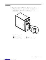
Page 72: ...64 User Guide ...

Page 73: ...warranty information that is provided with your computer for a list of service and support telephone numbers The monitor screen is blank Verify that v The monitor cable is securely attached to the rear of the monitor and to the rear of the computer v The monitor power cord is plugged into the monitor and into a working electrical outlet v The monitor is turned on and the brightness and contrast co...

Page 74: ...rrect the problem have the computer serviced Refer to the safety and warranty information that is provided with your computer for a list of service and support telephone numbers The operating system will not start Verify that v There is no diskette in the diskette drive v The startup sequence includes the device where the operating system resides Usually the operating system is on the hard disk dr...

Page 75: ...iagnose the computer problem The Lenovo System Toolbox also has problem determination aids that determine software and usage problems PC Doctor for Windows PE The PC Doctor for Windows PE diagnostic program is part of the Rescue and Recovery workspace on each Lenovo computer Use the PC Doctor for Windows PE if you are unable to start the Windows operating system or if the Lenovo System Toolbox has...

Page 76: ...the computer is turned on Then insert the disc into the optical drive 3 Turn the computer off and back on again When the diagnostics program opens follow the instructions on the screen Note When the program finishes be sure to remove the disc from the optical drive 4 Select the diagnostic test you want to run Press the F1 key for additional help Cleaning the mouse This section provides instruction...

Page 77: ...hat the retainer ring and ball fall out into your hand 5 Wash the ball in warm soapy water Then dry it with a clean cloth 6 Blow air carefully into the ball cage 4 to dislodge dust and lint 7 Look for a buildup of dirt on the plastic rollers 3 inside the ball cage This buildup usually appears as a stripe running across the middle of the rollers 8 If the rollers are dirty clean them by using a cott...

Page 78: ...11 Reconnect the mouse cable to the computer 12 Turn your computer back on 70 User Guide ...

Page 79: ...nstalled to view If the Adobe Reader has not yet been installed on your computer a message will appear when you attempt to view the PDF file and you will be guided through the Adobe Reader installation 2 The publications that are preinstalled on your computer are available in other languages on the Lenovo Support Web site at http www lenovo com support 3 If you want to install a different language...

Page 80: ...rovided with your computer contains information on safety setup warranty and notices Read and understand all safety information before using this product Lenovo Web site http www lenovo com The Lenovo Web site provides up to date information and services to help you buy upgrade and maintain your computer You can also do the following v Shop for Desktop and notebook computers Monitors Projectors Up...

Page 81: ...re repair If the problem is caused by hardware under warranty trained service personnel are available to provide the applicable level of service v Engineering Change management There might be changes that are required after a product has been sold Lenovo or your reseller will make selected Engineering Changes ECs that apply to your hardware available These items are not covered by the warranty v R...

Page 82: ...n countries might not be able to service all models of a particular machine type In some countries fees and restrictions might apply at the time of service To determine whether your computer is eligible for International Warranty Service and to view a list of the countries where service is available go to http www lenovo com support click Warranty and follow the instructions on the screen For tech...

Page 83: ...information could include technical inaccuracies or typographical errors Changes are periodically made to the information herein these changes will be incorporated in new editions of the publication Lenovo may make improvements and or changes in the product s and or the program s described in this publication at any time without notice The products described in this document are not intended for u...

Page 84: ...ection technology must be authorized by Macrovision Corporation and is intended for home and other limited viewing uses only unless otherwise authorized by Macrovision Corporation Reverse engineering or disassembly is prohibited European conformance CE mark Trademarks The following terms are trademarks of Lenovo in the United States other countries or both Lenovo Rescue and Recovery The Lenovo log...

Page 85: ... 73 D deleting password 58 device drivers 45 installing 54 recovering 54 devices handling static sensitive 13 diagnostics programs using 73 diagnostics troubleshooting 65 disc creating product recovery 49 diskette drive replacing 33 diskette creating and using a recovery repair 53 documentation using 73 drivers device 45 drives bays 22 internal 21 specifications 22 E environment operating 4 Ethern...

Page 86: ...y disc creating 49 productivity center ThinkVantage 71 programs updating system 61 protection password 46 purchasing additional services 74 R rear connectors 8 rear fan assembly replacing 40 recovering device drivers 54 from a POST BIOS update failure 62 information 49 recovery boot block 62 operations backup and 51 problems solving 55 repair diskette creating and using 53 workspace rescue and 51 ...

Page 87: ...U updating flashing BIOS 61 antivirus software 6 system programs 61 updating flashing BIOS 62 USB connector 9 using diagnostic programs 73 documentation 73 other services 74 passwords 57 recovery repair diskette creating and using 53 rescue media creating and 52 Setup Utility 57 utility program starting 57 V VGA monitor connector 9 video subsystem 1 viewing and changing settings 57 W warranty info...

Page 88: ...80 User Guide ...

Page 89: ......

Page 90: ...Part Number 53Y6337 Printed in USA 1P P N 53Y6337 ...

Reviews: