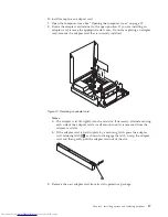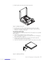
8.
Install
the
new
power
supply
assembly
into
the
chassis
so
that
the
screw
holes
in
the
new
power
supply
assembly
align
with
those
in
the
chassis.
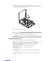
9.
Install
and
tighten
the
four
screws
at
the
rear
of
the
chassis
to
secure
the
power
supply
assembly.
Note:
Use
only
the
screws
provided
by
Lenovo.
10.
Reconnect
all
the
power
supply
assembly
cables
to
the
drives
and
the
system
board.
11.
Secure
the
power
supply
assembly
cables
with
the
cable
clips
and
ties
in
the
chassis.
12.
Go
to
“Completing
the
parts
replacement”
on
page
35.
Replacing
the
heat
sink
and
fan
assembly
Attention
Do
not
open
your
computer
or
attempt
any
repair
before
reading
and
understanding
the
“Important
safety
information”
in
the
ThinkCentre
Safety
and
Warranty
Guide
that
came
with
your
computer.
To
obtain
a
copy
of
the
ThinkCentre
Safety
and
Warranty
Guide
,
go
to:
http://www.lenovo.com/support
CAUTION:
The
heat
sink
and
fan
assembly
might
be
very
hot.
Turn
off
the
computer
and
wait
three
to
five
minutes
to
let
the
computer
cool
before
opening
the
computer
cover.
This
section
provides
instructions
on
how
to
replace
the
heat
sink
and
fan
assembly.
To
replace
the
heat
sink
and
fan
assembly:
1.
Open
the
computer
cover.
See
“Opening
the
computer
cover”
on
page
12.
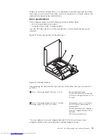
2.
Pivot
the
optical
drive
bay
assembly
upward
to
gain
easy
access
to
the
heat
sink
and
fan
assembly.
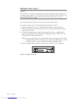
3.
Disconnect
the
heat
sink
and
fan
assembly
cable
from
the
system
board.
See
“Locating
parts
on
the
system
board”
on
page
10.
Chapter
2.
Installing
options
and
replacing
hardware
31
Summary of Contents for 7360APU
Page 1: ......
Page 2: ......
Page 3: ...ThinkCentre User Guide ...
Page 6: ...iv User Guide ...
Page 8: ...vi User Guide ...
Page 54: ...46 User Guide ...
Page 62: ...54 User Guide ...
Page 78: ...70 User Guide ...
Page 79: ......
Page 80: ...Part Number 53Y9876 Printed in USA 1P P N 53Y9876 ...

