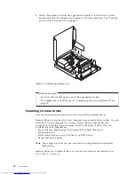


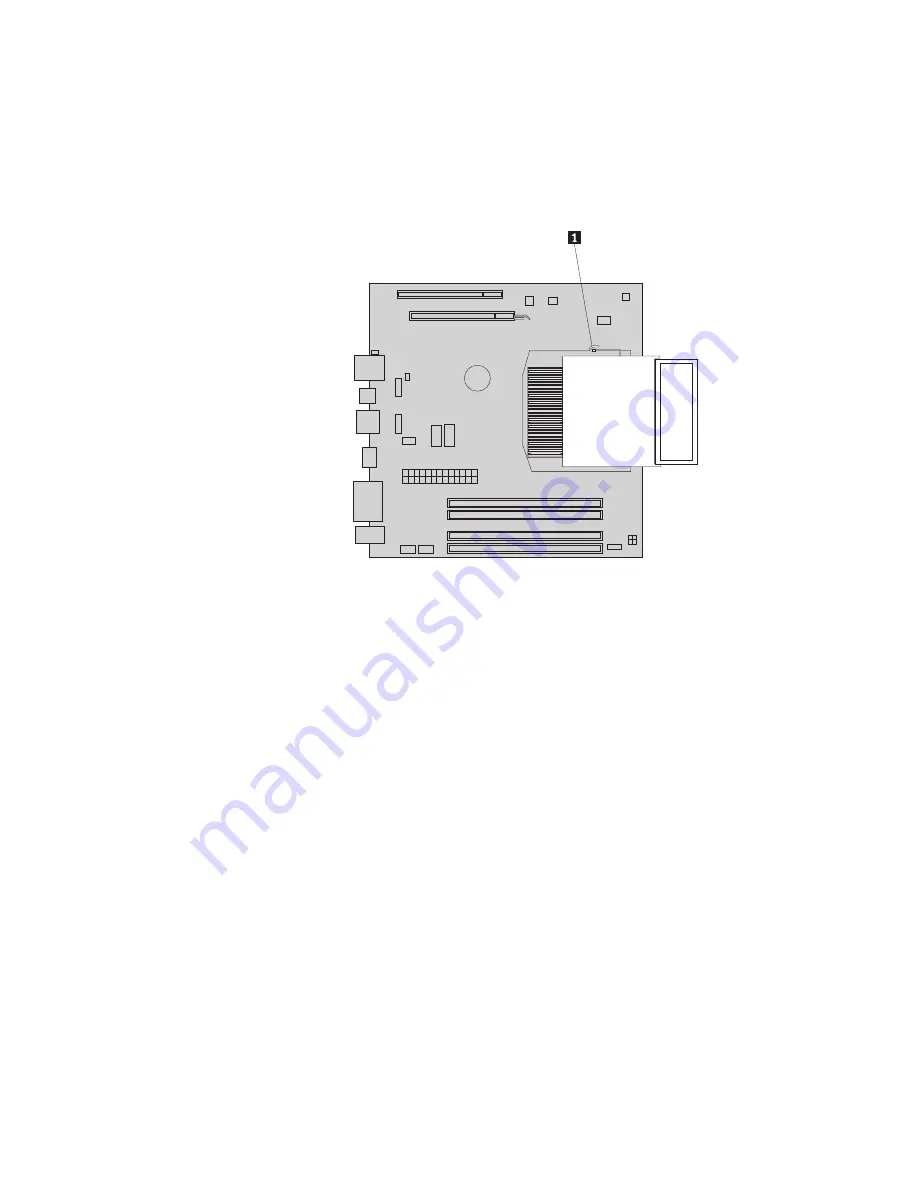
4.
Remove
the
heat
sink
and
fan
assembly
from
the
system
board
by
pivoting
the
lever
1
that
secures
the
heat
sink
and
fan
assembly
until
it
is
fully
in
the
up
position.
Note:
It
helps
to
remove
the
hard
disk
drive
before
this
step.
See
“Replacing
the
hard
disk
drive”
on
page
22.
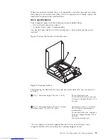
5.
Carefully
lift
the
heat
sink
and
fan
assembly
off
the
system
board.
Notes:
a.
You
might
have
to
gently
twist
the
heat
sink
and
fan
assembly
to
free
it
from
the
microprocessor.
b.
Do
not
touch
the
thermal
grease
while
handling
the
heat
sink
and
fan
assembly.
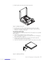
6.
Place
the
new
heat
sink
and
fan
assembly
into
position
and
lower
the
lever
to
secure
the
new
heat
sink
and
fan
assembly.
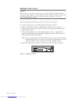
7.
Connect
the
heat
sink
and
fan
assembly
cable
to
the
microprocessor
fan
connector
on
the
system
board.
See
“Locating
parts
on
the
system
board”
on
page
10.
8.
Go
to
“Completing
the
parts
replacement”
on
page
35.
Figure
27.
Removing
the
heat
sink
and
fan
assembly
32
User
Guide
Summary of Contents for 7360APU
Page 1: ......
Page 2: ......
Page 3: ...ThinkCentre User Guide ...
Page 6: ...iv User Guide ...
Page 8: ...vi User Guide ...
Page 54: ...46 User Guide ...
Page 62: ...54 User Guide ...
Page 78: ...70 User Guide ...
Page 79: ......
Page 80: ...Part Number 53Y9876 Printed in USA 1P P N 53Y9876 ...


