


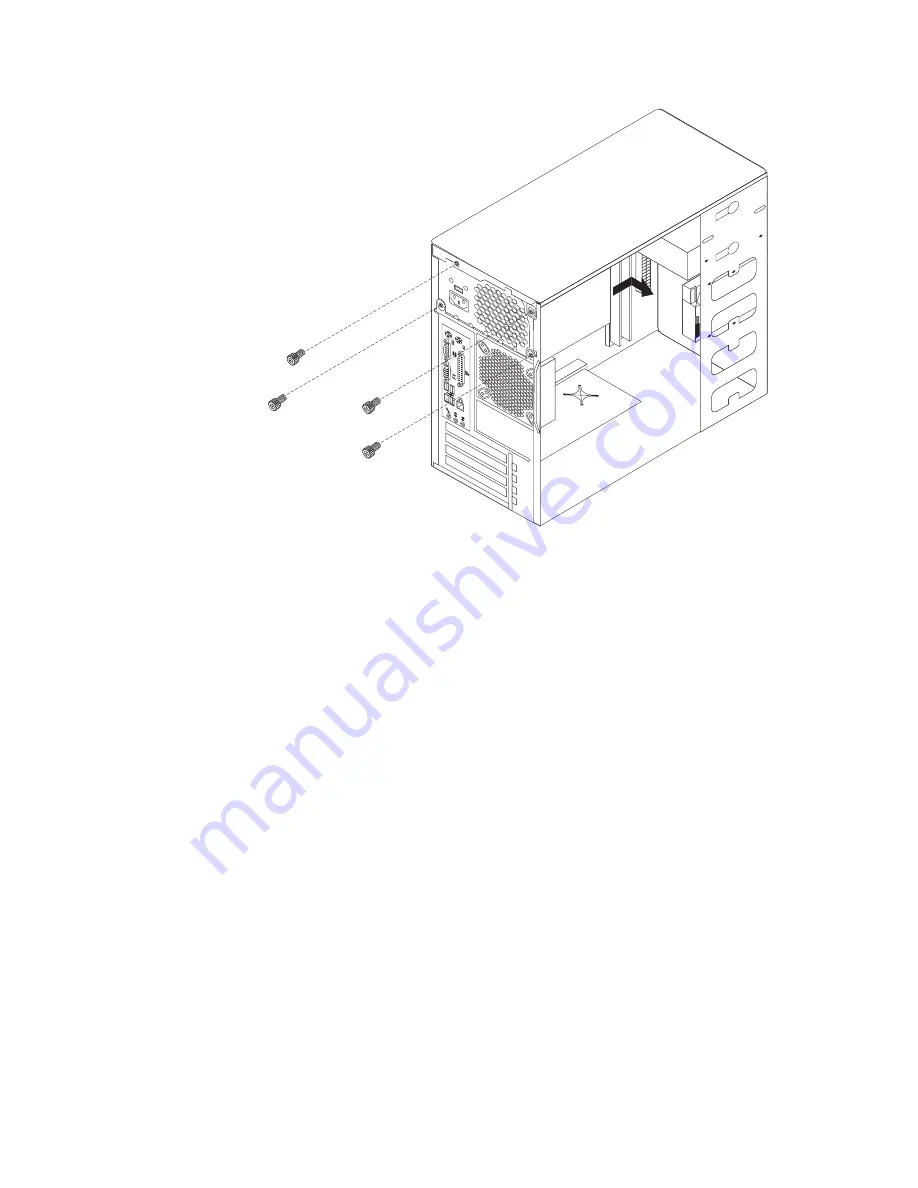
5.
Lift
the
power
supply
out
of
the
chassis.
6.
Install
the
new
power
supply
and
insert
the
four
screws
that
hold
the
power
supply
in
place.
7.
Reconnect
all
power
supply
cables
to
the
system
board
and
the
drives.
See
“Identifying
parts
on
the
system
board”
on
page
85.
Make
sure
the
cables
are
correctly
routed.
8.
Go
to
“Completing
the
FRU
replacement”
on
page
107.
96
Lenovo
E200
Hardware
Maintenance
Manual
Summary of Contents for 7848
Page 1: ......
Page 2: ......
Page 3: ...Lenovo E200 Hardware Maintenance Manual ...
Page 6: ...iv Lenovo E200 Hardware Maintenance Manual ...
Page 10: ...4 Lenovo E200 Hardware Maintenance Manual ...
Page 18: ...12 Lenovo E200 Hardware Maintenance Manual ...
Page 19: ...Chapter 2 Safety information 13 ...
Page 20: ... 18 kg 37 lbs 32 kg 70 5 lbs 55 kg 121 2 lbs 1 2 14 Lenovo E200 Hardware Maintenance Manual ...
Page 24: ...18 Lenovo E200 Hardware Maintenance Manual ...
Page 25: ...1 2 Chapter 2 Safety information 19 ...
Page 26: ...20 Lenovo E200 Hardware Maintenance Manual ...
Page 27: ...1 2 Chapter 2 Safety information 21 ...
Page 34: ...28 Lenovo E200 Hardware Maintenance Manual ...
Page 35: ...Chapter 2 Safety information 29 ...
Page 36: ...1 2 30 Lenovo E200 Hardware Maintenance Manual ...
Page 40: ...34 Lenovo E200 Hardware Maintenance Manual ...
Page 41: ...1 2 Chapter 2 Safety information 35 ...
Page 54: ...48 Lenovo E200 Hardware Maintenance Manual ...
Page 58: ...52 Lenovo E200 Hardware Maintenance Manual ...
Page 86: ...80 Lenovo E200 Hardware Maintenance Manual ...
Page 114: ...108 Lenovo E200 Hardware Maintenance Manual ...
Page 123: ......
Page 124: ...Part Number 36 LNV LC00121 Printed in USA 1P P N 36 LNV LC00121 ...


