background image

iv


User


Guide

Summary of Contents for 81712CU

Page 1: ...ThinkCentre User Guide Types 8424 8425 8428 Types 8171 8172 8173 ...

Page 2: ......

Page 3: ...ThinkCentre User Guide Types 8424 8425 8428 Types 8171 8172 8173 ...

Page 4: ...nt safety information on page v and Appendix D Notices on page 41 First Edition April 2004 Copyright International Business Machines Corporation 2004 All rights reserved US Government Users Restricted Rights Use duplication or disclosure restricted by GSA ADP Schedule Contract with IBM Corp ...

Page 5: ...talling security features 20 Identifying security locks 21 Integrated security cable 21 Rope clip 23 Cover lock 23 Password protection 23 Erasing a lost or forgotten password clearing CMOS 24 Closing the cover and connecting the cables 24 Chapter 3 Using the IBM Setup Utility 25 Starting the IBM Setup Utility program 25 Viewing and changing settings 25 Exiting from the IBM Setup Utility program 25...

Page 6: ...iv User Guide ...

Page 7: ...ugged so the battery safety information applies to all computers Conditions that require immediate action Products can become damaged due to misuse or neglect Some product damage is serious enough that the product should not be used again until it has been inspected and if necessary repaired by an authorized servicer As with any electronic device pay close attention to the product when it is turne...

Page 8: ...omer These parts are referred to as Customer Replaceable Units or CRUs IBM expressly identifies CRUs as such and provides documentation with instructions when it is appropriate for customers to replace those parts You must closely follow all instructions when performing such replacements Always make sure that the power is turned off and that the product is unplugged from any power source before yo...

Page 9: ...ts only into a grounded electrical outlet This is a safety feature Do not defeat this safety feature by trying to insert it into a non grounded outlet If you cannot insert the plug into the outlet contact an electrician for an approved outlet adapter or to replace the outlet with one that enables this safety feature Never overload an electrical outlet The overall system load should not exceed 80 p...

Page 10: ...t with the body could cause discomfort or potentially a skin burn v Do not operate your computer or charge the battery near flammable materials or in explosive environments v Ventilation slots fans and or heat sinks are provided with the product for safety comfort and reliable operation These features might inadvertently become blocked by placing the product on a bed sofa carpet or other flexible ...

Page 11: ...et des câbles de transmission peut présenter un danger Pour éviter tout risque de choc électrique v Ne manipulez aucun câble et n effectuez aucune opération d installation d entretien ou de reconfiguration de ce produit au cours d un orage v Branchez tous les cordons d alimentation sur un socle de prise de courant correctement câblé et mis à la terre v Branchez sur des socles de prise de courant c...

Page 12: ...ired by local ordinances or regulations ATTENTION Danger d explosion en cas de remplacement incorrect de la batterie Remplacer uniquement par une batterie IBM de type ou d un type équivalent recommandé par le fabricant La batterie contient du lithium et peut exploser en cas de mauvaise utilisation de mauvaise manipulation ou de mise au rebut inappropriée Ne pas v Lancer ou plonger dans l eau v Cha...

Page 13: ...puter models are equipped from the factory with a CD ROM drive or a DVD ROM drive CD ROM drives and DVD ROM drives are also sold separately as options CD ROM drives and DVD ROM drives are laser products These drives are certified in the U S to conform to the requirements of the Department of Health and Human Services 21 Code of Federal Regulations DHHS 21 CFR Subchapter J for Class 1 laser product...

Page 14: ... de CD ROM DVD ROM est installée tenez compte des remarques suivantes ATTENTION Pour éviter tout risque d exposition au rayon laser respectez les consignes de réglage et d utilisation des commandes ainsi que les procédures décrites L ouverture de l unité de CD ROM DVD ROM peut entraîner un risque d exposition au rayon laser Pour toute intervention faites appel à du personnel qualifié Certaines uni...

Page 15: ...option Information resources The Quick Reference that comes with your computer provides information for setting up your computer starting the operating system troubleshooting and notices Access IBM provides a link to more information about your computer Click Start Access IBM If you have Internet access the most up to date manuals for your computer are available from the World Wide Web To access t...

Page 16: ...isk drive v CD ROM DVD ROM DVD ROM CD RW Combo CD RW or Rambo III IV DVD RAM Multi Burner optical drive some models Video subsystem Intel Graphics Media Accelerator 900 with dual display support Audio subsystem The integrated AC 97 audio controller provides four audio connectors v Microphone and headphone connectors on the front panel v Line in and line out connectors on the rear panel v Mono inte...

Page 17: ...res The IBM Embedded Security Subsystem ESS is a security subsystem included on IBM ThinkCentre PCs It consists of a dedicated Hardware Security Module built on to the motherboard and Client Security Software a free web downloaded application ESS provides the following security values by enhancing the security of v data stored on the PC by providing an encryption application File and Folder Encryp...

Page 18: ...isk I O control v Serial and parallel port I O control v Security profile by device IBM preinstalled software Your computer comes with preinstalled software An operating system device drivers to support built in features and other support programs are included 4 User Guide ...

Page 19: ...ternal options System memory called dual inline memory modules DIMMs Peripheral component interconnect PCI adapters PCI Express x1 adaptors CD ROM DVD ROM or CD RW drive hard disk drive diskette drive and other removable media drives For the latest information about available options see the following World Wide Web pages v http www ibm com pc us options v http www ibm com pc support You can also ...

Page 20: ...ly 14 cubic feet 0 45 cubic meters per minute Acoustical noise emission values Note In this computer fan speed is controlled by temperature configuration and software Actual noise emission values might be different from the stated values depending on the number of fans and the speed of the fans Average sound pressure levels for computers with a microprocessor that runs at or below 2 8 GHz At opera...

Page 21: ...Supported operating positions To provide proper air flow to internal components you must position your computer in one of the positions as illustrated below Chapter 1 Overview 7 ...

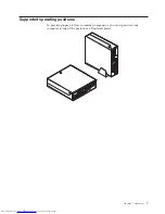
Page 22: ...8 User Guide ...

Page 23: ...m touching components v When you install a new option touch the static protective package containing the option to a metal expansion slot cover or other unpainted metal surface on the computer for at least two seconds This reduces static electricity in the package and your body v When possible remove the option and install it directly in the computer without setting the option down When this is no...

Page 24: ...cations of the controls and connectors on the front of your computer 1 Cover keylock some models 6 USB connectors 2 2 CD or DVD drive 7 Microphone connector line in 3 Hard disk drive activity indicator 8 Headphone connector line out 4 Power on indicator 9 Diskette drive 5 Power button 10 User Guide ...

Page 25: ...s 4 5 Serial connectors 2 13 PS 2 keyboard connector 6 Ethernet connector 14 PS 2 mouse connector 7 USB connectors 2 15 LEDs 8 VGA monitor connector Note Some connectors on the rear of your computer are color coded to help determine where to connect the cables Obtaining device drivers You can obtain device drivers for operating systems that are not preinstalled at http www ibm com pc support on th...

Page 26: ...he drives and turn off all attached devices and the computer 2 Unplug all power cords from electrical outlets 3 Disconnect all cables attached to the computer This includes power cords input output I O cables and any other cables that are connected to the computer 4 Remove the floor stand if attached 5 If a cover lock is installed unlock the cover 6 Press inward on the two buttons and rotate the t...

Page 27: ... you locate the various components in your computer 1 Diskette drive lock 5 Power supply assembly 2 DIMM memory connectors 2 6 CD or DVD drive hard disk drive is under the CD drive 3 Battery 7 CD or DVD drive lock 4 PCI riser Chapter 2 Installing options 13 ...

Page 28: ...s To access system board components and the drives 1 Turn off the computer 2 Open the cover See Opening the cover on page 12 3 Rotate the drive bay assembly upward as illustrated Note Make sure you note the location of any cables that you disconnect from the drives or the system board 4 If any PCI adapters are installed remove the PCI riser and adapter cards Do not remove any adapters from the ris...

Page 29: ...llustration shows the locations of parts on the system board 1 Fan connectors 2 8 Diskette drive connector 2 Memory DIMM connectors 2 9 Power button and front LED assembly connector 3 SATA IDE hard disk drive connectors 2 10 Power supply connector 4 Riser connector 11 PATA Primary IDE connector hard disk drive and CD ROM drive 5 CMOS Battery 12 Power supply connector 6 Clear CMOS BIOS recovery jum...

Page 30: ...AM DIMMs can be used To install DIMMs 1 Access the system board See Accessing system board components and drives on page 14 2 Locate the DIMM connectors See Identifying parts on the system board on page 15 3 Open the retaining clips 4 Make sure the notch in the DIMM aligns with the tab on the connector Push or insert the memory module straight down into the connector until the retaining clips clos...

Page 31: ...le holding the left rear of the computer chassis down pull upward on the handle provided to remove the PCI riser and any adapters that are currently installed 3 Release the slot cover latch and remove the slot cover for the appropriate expansion slot 4 Remove the adapter from its static protective package 5 Install the adapter into the appropriate slot in the PCI riser Note The top slot is for the...

Page 32: ...ires no charging or maintenance throughout its life however no battery lasts forever If the battery fails the date time and configuration information including passwords are lost An error message is displayed when you turn on the computer Refer to Lithium battery notice on page x for information about replacing and disposing of the battery Important Before you install or remove any component read ...

Page 33: ...time and any passwords Removing and replacing an optical drive 1 Open the cover See Opening the cover on page 12 2 Rotate the drive bay assembly upward to gain access to the cable connections See Accessing system board components and drives on page 14 and Locating components on page 13 3 Disconnect the signal and power cables from the drive 4 Slide the lock 1 to the unlocked position 5 Open the do...

Page 34: ... drive 4 Rotate the drive bay assembly upward and remove the diskette drive To install a new diskette drive 1 Slide the new drive partially into the bay from the rear 2 Connect the flat cable to the new drive 3 Slide the new drive completely into the bay and slide the lock 1 to the locked position 4 See Closing the cover and connecting the cables on page 24 to finish the procedure Installing secur...

Page 35: ...sington lock 3 Cover lock Integrated security cable With an integrated cable lock sometimes referred to as the Kensington lock you can secure your computer to a desk table or other non permanent fixture The cable lock attaches to a security slot at the rear of your computer and is operated with a key This is the same type of lock used with many laptop computers You can order a security cable direc...

Page 36: ... 22 User Guide ...

Page 37: ...e sized wrench 4 Replace the cover 5 Thread the security cable through the rope clip and around an object that is not part of or permanently attached to the building structure or foundation and from which it cannot be removed then fasten the cable together with a lock Cover lock Your computer comes with a built in key lock or a provision to install a key lock such as those provided by the Illinois...

Page 38: ...ing the cover and connecting the cables After working with options you need to install any removed parts close the cover and reconnect cables including telephone lines and power cords Also depending on the option that is installed you might need to confirm the updated information in the IBM Setup Utility program To close the cover and connect cables to your computer 1 Ensure that all components ha...

Page 39: ...played until you type your password See Using passwords for more information The IBM Setup Utility might start automatically when POST detects that hardware has been removed or new hardware has been installed in your computer Viewing and changing settings The IBM Setup Utility program menu lists items that identify system configuration topics When working with the IBM Setup Utility program menu yo...

Page 40: ...mputer is turned on The computer cannot be used until a valid password is typed from the keyboard Administrator Password Setting an Administrator Password deters unauthorized persons from changing configuration settings If you are responsible for maintaining the settings of several computers you might want to set an Administrator Password After you set an Administrator Password a password prompt i...

Page 41: ...Select Set Passwords Read the information displayed on the right side of the screen Using Security Profile by Device Security Profile by Device is used to enable or disable user access to the following devices IDE controller When this feature is set to Disable all devices connected to the IDE controller such as hard disk drives or the CD ROM drive are disabled and will not be displayed in the syst...

Page 42: ...e following 1 Start the IBM Setup Utility program see Starting the IBM Setup Utility program on page 25 2 Select Startup 3 Select Startup Sequence See the information displayed on the right side of the screen 4 Select the devices for the Primary Startup Sequence the Automatic Startup Sequence and the Error Startup Sequence 5 Select Exit from the IBM Setup Utility menu and then Save Settings or Sav...

Page 43: ...de Web see the Quick Reference Instructions for using the POST BIOS updates are available in a txt file that is included with the update files For most models you can download either an update program to create a system program update flash diskette or an update program that can be run from the operating system Note You can download a self starting bootable CD image known as an iso image of the di...

Page 44: ...d components and drives on page 14 to gain access to the Clear CMOS BIOS Recovery jumper 5 Remove any cables or adapters that impede access to the Clear CMOS BIOS Recovery jumper 6 Move the jumper from the standard position pins 1 and 2 to pins 2 and 3 7 Replace any cables or adapters that were removed 8 Close the cover See Closing the cover and connecting the cables on page 24 9 Reconnect the pow...

Page 45: ...otton swab or plain q tip b If there is some debris in the lens gently blow the debris away from the area 2 Check the surface you are using the mouse on If you have a very intricate picture or pattern beneath the mouse it is difficult for the digital signal processor DSP to determine changes in the mouse position Cleaning a mouse with a ball If the pointer on the screen does not move smoothly with...

Page 46: ...efully into the ball cage 4 to dislodge dust and lint 5 Look for a build up of dirt on the plastic rollers 3 inside the ball cage This build up usually appears as a stripe running across the middle of the rollers 6 If the rollers are dirty clean them by using a cotton swab soaked in isopropyl rubbing alcohol Turn the rollers with your finger and continue swabbing them until all the dirt is removed...

Page 47: ...equires one it is just like specifying a parameter of 0 Example ATH ENTER Basic AT commands In the following listings all default settings are printed in bold text Command Function A Manually answer incoming call A Repeat last command executed Do not precede A with AT or follow with ENTER D_ 0 9 A D and L last number redial P pulse dialing Note Pulse dialing is not supported for Australia New Zeal...

Page 48: ...turn to Data Mode O1 Return to Data Mode and initiate an equalizer retrain P Set Pulse dial as default Q_ Q0 Modem sends responses Sr Read and display value in register r Sr n Set register r to value n n 0 255 T Set Tone Dial as default V_ V0 Numeric responses V1 Word responses W_ W0 Report DTE speed only W1 Report line speed error correction protocol and DTE speed W2 Report DCE speed only X_ X0 H...

Page 49: ...low control M_ M0 Asynchronous operation P_ P0 US setting for off hook to on hook ratio P1 UK and Hong Kong off hook to on hook ratio P2 Same as P0 setting but at 20 pulses per minute P3 Same as P1 setting but at 20 pulses per minute R_ R0 Reserved R1 CTS operates per flow control requirements S_ S0 Force DSR Signal High ON S1 DSR off in command mode on in on line mode T_ T0 Ends test in progress ...

Page 50: ... Parameter b specifies automode operations where 0 automode disabled 1 automode enabled with V 8 V 32 Annex A Parameter c specifies the minimum connection data rate 300 56000 Parameter d specifies the maximum connection rate 300 56000 Parameter e specifies the codec type 0 Law and 1 A Law Parameter f specifies robbed bit signaling detection 0 detection disabled 1 detection enabled MNP V 42 V 42bis...

Page 51: ... Set the polled station identification FCIG Report the polled station identification FCR Capability to receive FCR Capability to receive FCSI Report the called station ID FDCC DCE capabilities parameters FDCS Report current session FDCS Current session results FDIS Report remote capabilities FDIS Current sessions parameters FDR Begin or continue phase C receive data FDT Data transmission FDTC Repo...

Page 52: ...ufacturer REV Identify Revision Level TL Audio output transmit level VBQ Query Buffer Size VBS Bits per sample ADPCM or PCM VBT Beep Tone Timer VCI Identify Compression Method VLS Voice line select VRA Ringback goes away timer VRN Ringback never came timer VRX Voice Receive Mode VSDB Silence deletion tuner VSK Buffer skid setting VSP Silence detection period VSR Sampling rate selection VSS Silence...

Page 53: ...s not have Taxsignal switched OFF modem function may be impaired The impairment may be resolved by a filter with the following specifications Telekom PTT SCR BE Taximpulssperrfilter 12kHz PTT Art 444 112 7 Bakom 93 0291 Z N Appendix C Manual modem commands 39 ...

Page 54: ...40 User Guide ...

Page 55: ...s in certain transactions therefore this statement may not apply to you This information could include technical inaccuracies or typographical errors Changes are periodically made to the information herein these changes will be incorporated in new editions of the publication IBM may make improvements and or changes in the product s and or the program s described in this publication at any time wit...

Page 56: ...e Wake on LAN Intel Celeron and Pentium are trademarks of Intel Corporation in the United States other countries or both Microsoft Windows and Windows NT are trademarks of Microsoft Corporation in the United States other countries or both Other company product and service names may be trademarks or service marks of others 42 User Guide ...

Page 57: ...20 double data rate DDR memory 16 drives installing 14 E environment operating 6 error startup sequence 28 Ethernet 2 exiting Setup Utility 25 expansion adapters 3 external options 9 F features 2 H hard disk drive security 25 hyper threading 28 I IBM Setup Utility 25 information resources 1 input output I O features 3 installing options adapters 17 cable lock 20 drives 14 memory 16 internal drives...

Page 58: ...attery 18 diskette drive 20 memory 16 optical drive 19 riser card 17 S security cable lock 20 features 3 hard disk drive 25 profile by device 27 selecting startup device 28 temporary startup device 28 software 4 specifications 6 startup sequence 28 system board components accessing 14 connectors 15 identifying parts 15 location 15 memory 5 16 system management 2 U updating BIOS diskette 29 OS 29 u...

Page 59: ......

Page 60: ... Part Number 19R0474 Printed in USA 1P P N 19R0474 ...

Reviews: