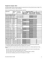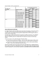
For the x480 X6 or x880 X6, if two compute nodes are scaled together, then a maximum of 3 scaled
complexes can be installed. For the x880 X6, if four compute nodes are scaled together, then a maximum
of 1 scaled x880 X6 complexes can be installed. Other bays can be filled with other compute nodes.
The table in the
Power Supplies
section provides guidelines about what number of compute nodes can be
powered on in the Enterprise Chassis, based on the type and number of power supplies installed.
See ServerProven® for the latest information about the supported servers:
http://www.lenovo.com/us/en/serverproven/flexsystem.shtml
Supported I/O modules
The Flex System Enterprise Chassis has four high-speed switch bays that are capable of supporting a
variety of I/O architectures.
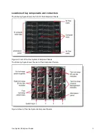
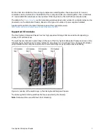
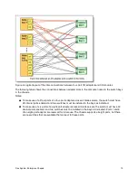
The switches are installed in switch bays in the rear of the Flex System Enterprise Chassis as shown in the
following figure. Switches are normally installed in pairs (bays 1 & 2, and bays 3 & 4), because I/O adapter
cards installed in the compute nodes route to two switch bays for performance and redundancy.
Figure 4. Location of the switch bays in the Flex System Enterprise Chassis
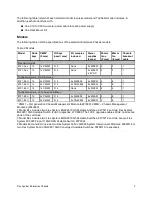
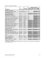
The following table lists the switches that are supported by the chassis.
Note: Some switches are withdrawn from marketing.
Flex System Enterprise Chassis
7


