
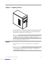


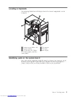


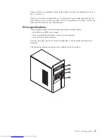


Locating
components
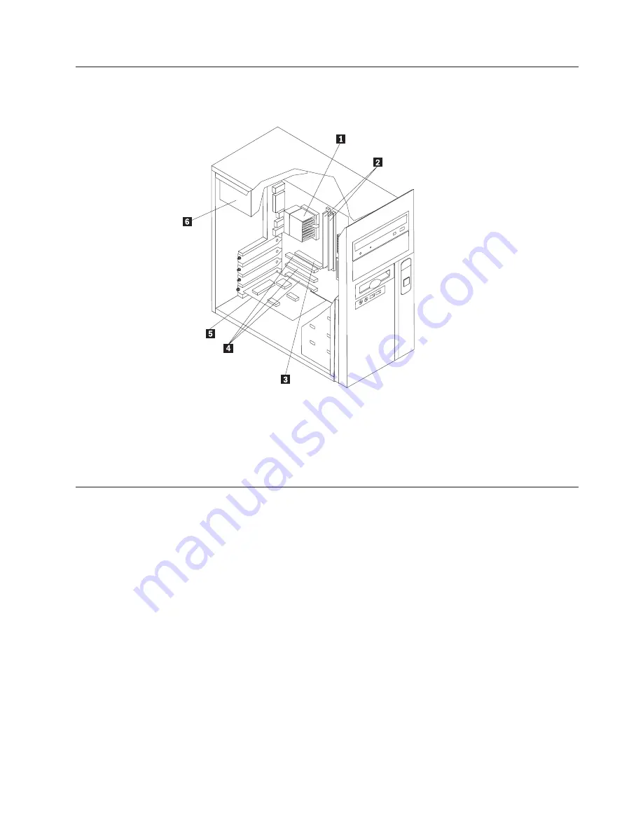
The
following
illustration
will
help
you
locate
the
various
components
in
your
computer.
1
Microprocessor
and
heat
sink
4
PCI
connectors
2
Memory
modules
5
PCI
adapter
3
AGP
adapter
or
PCI
Express
x16
adapter
graphics
connector
(some
models)
6
Power
supply
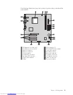
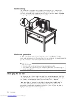
Identifying
parts
on
the
system
board
The
system
board
(sometimes
called
the
planar
or
motherboard
)
is
the
main
circuit
board
in
your
computer.
It
provides
basic
computer
functions
and
supports
a
variety
of
devices
that
are
factory-installed
or
that
you
can
install
later.
Chapter
1.
Installing
options
11
Summary of Contents for 921525U
Page 2: ......
Page 6: ...iv User Guide ...
Page 16: ...xiv User Guide ...
Page 46: ...30 User Guide ...
Page 50: ...34 User Guide ...
Page 52: ...36 User Guide ...
Page 62: ...46 User Guide ...
Page 67: ......
Page 68: ...Part Number 41D2698 Printed in USA 1P P N 41D2698 ...


