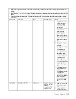
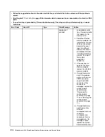
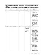

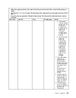
• Follow the suggested actions in the order in which they are listed in the Action column until the problem is
solved.
• See Chapter 3 “
Parts listing
” on page 29 to determine which components are consumable, structural, or CRU
parts.
• If an action step is preceded by “(Trained technician only),” that step must be performed only by a trained
technician.
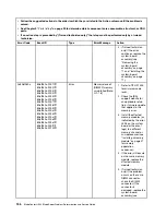
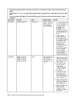
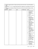
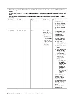
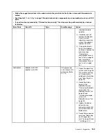
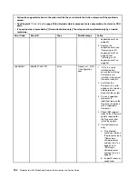
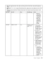
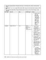
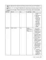
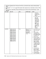
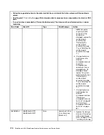
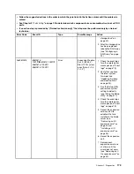
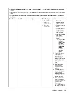
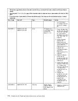
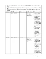
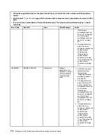
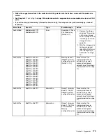
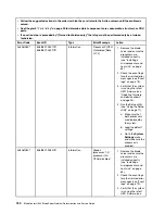
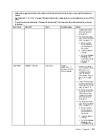
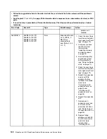
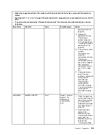
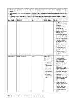
Error Code
Event ID
Type
Error Message
Action
logging limit
reached
an applicable retain
tip or firmware update
that applies to this
memory error.
3. Swap the affected
memory modules (as
indicated by the error
LEDs on the system
board or the event
logs) to a different
memory channel or
microprocessor (see
“Installing a memory
module” on page 47
for memory
population
sequence).
4. If the error occurs
again on the same
memory module,
replace the affected
memory module.
5. (Trained technician
only) If the problem
occurs on the same
DIMM connector,
check the DIMM
connector. If the
connector is
damaged, replace the
system-board
assembly (see
“Removing the
system-board
assembly” on page
71 and “Installing the
system-board
assembly” on page
71).
6. (Trained technician
only) Remove the
affected
microprocessor and
check the
microprocessor
socket pins for any
damaged pins. If a
damage is found,
replace the system-
board assembly (see
170
BladeCenter HS23 Blade ServerProblem Determination and Service Guide
Summary of Contents for BladeCenter HS23 1929
Page 1: ...BladeCenter HS23 Blade Server Problem Determination and Service Guide Machine Types 7875 1929 ...
Page 284: ...268 BladeCenter HS23 Blade ServerProblem Determination and Service Guide ...
Page 289: ...Taiwan BSMI RoHS declaration Appendix B Notices 273 ...
Page 290: ...274 BladeCenter HS23 Blade ServerProblem Determination and Service Guide ...
Page 296: ...280 BladeCenter HS23 Blade ServerProblem Determination and Service Guide ...
Page 297: ......
Page 298: ...Part Number 00KC215 Printed in China 1P P N 00KC215 ...
Page 299: ... 1P00KC215 ...


