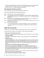
• If no LEDs are lit on the blade server front panel, verify the blade server status and errors in the Advanced-
Management-Module Web interface; also see “Solving undetermined problems” on page 262.
• If device errors occur, see “Troubleshooting tables” on page 188.
Performing the checkout procedure
Use this information to perform the checkout procedure for the blade server.
To perform the checkout procedure, complete the following steps:
Step 1. If the blade server is running, turn off the blade server.
Step 2. Turn on the blade server. Make sure that the blade server has control of the video (the LED on the
keyboard/video/mouse button is lit). If the blade server does not start, see “Troubleshooting tables”
on page 188.
Step 3. Record any POST error messages that are displayed on the monitor. If an error is displayed, look
up the first error in the “POST/UEFI diagnostic codes” on page 81.
Step 4. Check the control panel blade-error LED; if it is lit, check the light path diagnostics LEDs (see “Light
path diagnostics” on page 204).
Step 5. Check for the following results:
• Successful completion of POST, indicated by beginning the startup of the operating system.
• Successful completion of startup, indicated by a readable display of the operating-system
desktop.
Diagnostic tools overview
Use this overview to locate specific diagnostic tools to diagnose and solve hardware-related problems.
The following tools are available to help you diagnose and solve hardware-related problems:
•
POST codes, error messages, and error logs
The POST error codes indicate the detection of a problem. For more information, see “POST” on page 81.
•
Troubleshooting tables
These tables list problem symptoms and actions to correct the problems. See “Troubleshooting tables”
on page 188
•
Light path diagnostics
Use light path diagnostics LEDs on the system board to diagnose system errors. If the system-error LED
on the system LED panel on the front or rear of the BladeCenter unit is lit, one or more error LEDs on the
BladeCenter unit components also might be lit. These LEDs help identify the cause of the problem. For
more information about the blade server error LEDs, see “Blade server light path diagnostics LEDs” on
page 205.
•
Dynamic System Analysis (DSA) Portable Edition diagnostic program
DSA tests the major components of the BladeCenter unit, including the management modules, I/O
modules, removable-media drives, and the blade servers, while the operating system is running. For
documentation and download information for DSA, see http://www.ibm.com /systems/management/. For
more information about diagnostic programs and error messages, see “IBM Dynamic System Analysis
Preboot diagnostic program” on page 209
Note:
If you are unable to find the system-error logs in the blade server firmware code, view the system-
event log in the BladeCenter management module.
•
Dynamic System Analysis (DSA) Preboot diagnostic program
78
BladeCenter HS23 Blade ServerProblem Determination and Service Guide
Summary of Contents for BladeCenter HS23 1929
Page 1: ...BladeCenter HS23 Blade Server Problem Determination and Service Guide Machine Types 7875 1929 ...
Page 284: ...268 BladeCenter HS23 Blade ServerProblem Determination and Service Guide ...
Page 289: ...Taiwan BSMI RoHS declaration Appendix B Notices 273 ...
Page 290: ...274 BladeCenter HS23 Blade ServerProblem Determination and Service Guide ...
Page 296: ...280 BladeCenter HS23 Blade ServerProblem Determination and Service Guide ...
Page 297: ......
Page 298: ...Part Number 00KC215 Printed in China 1P P N 00KC215 ...
Page 299: ... 1P00KC215 ...

