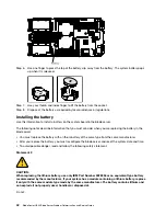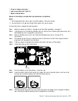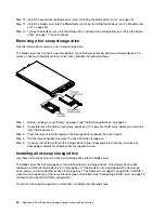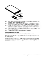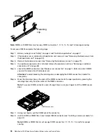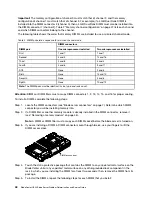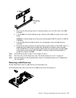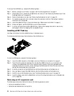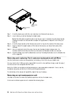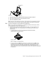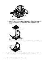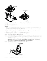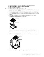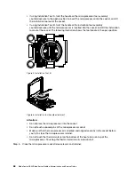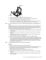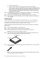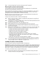
Step 1. Before you begin, read “Safety” on page iii and “Installation guidelines” on page 37.
Step 2. If the blade server is installed in a BladeCenter unit, remove it (see “Removing the blade server from
the BladeCenter unit” on page 39).
Step 3. Remove the blade server cover (see “Installing the blade server cover” on page 73).
Step 4. If an optional expansion unit is installed, remove the expansion unit (see “Removing an optional
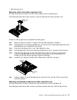
Step 5. Remove the bezel assembly (see “Removing the bezel assembly” on page 74).
Step 6. Locate the control-panel connector on the system board (see “Blade server connectors” on page
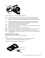
7).
Step 7. Using your fingers, pull the control-panel cable out of the connector; then lift the control panel from
the blade server.
Step 8. If you are instructed to return the control panel, follow all packaging instructions, and use any
packaging materials for shipping that are supplied to you.
Installing the control panel
Use these instructions to install the control panel in the blade server.
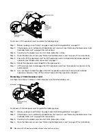
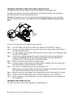
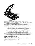
The blade server has a control panel that provides controls and information LEDs for the blade server (see
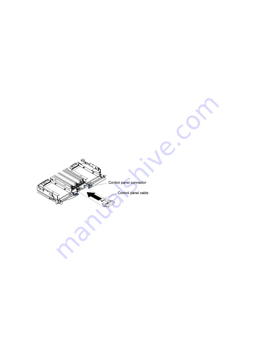
“Blade server controls and LEDs” on page 4). The following illustration shows how to install the control panel.
To install the control panel, complete the following steps:
Step 1. Locate the control-panel connector on the blade server (see “Blade server connectors” on page 7).
Step 2. Touch the static-protective package that contains the control panel to any
unpainted
metal surface
on the BladeCenter unit or any
unpainted
metal surface on any other grounded rack component in
the rack in which you are installing the control panel for at least two seconds; then, remove the
USB module from its package.
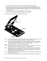
Step 3. Orient the control panel so the cable aligns with the control-panel connector and the control panel
is positioned at the front of the blade server.
Step 4. Use your fingers to install the control-panel cable into the control-panel connector on the blade
server.
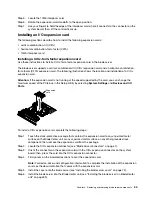
Step 5. Install the bezel assembly (see “Installing the bezel assembly” on page 75).
Step 6. Install the optional expansion unit, if you removed one from the blade server to replace the battery
(see “Installing an optional expansion unit” on page 59 for instructions).
Step 7. Install the cover onto the blade server (see “Installing the blade server cover” on page 73).
Step 8. Install the blade server into the BladeCenter unit (see “Installing the blade server in a BladeCenter
56
BladeCenter HS23 Blade ServerProblem Determination and Service Guide
Summary of Contents for BladeCenter HS23 1929
Page 1: ...BladeCenter HS23 Blade Server Problem Determination and Service Guide Machine Types 7875 1929 ...
Page 284: ...268 BladeCenter HS23 Blade ServerProblem Determination and Service Guide ...
Page 289: ...Taiwan BSMI RoHS declaration Appendix B Notices 273 ...
Page 290: ...274 BladeCenter HS23 Blade ServerProblem Determination and Service Guide ...
Page 296: ...280 BladeCenter HS23 Blade ServerProblem Determination and Service Guide ...
Page 297: ......
Page 298: ...Part Number 00KC215 Printed in China 1P P N 00KC215 ...
Page 299: ... 1P00KC215 ...

