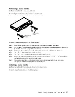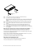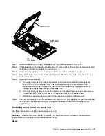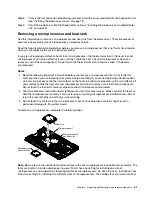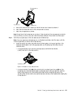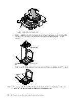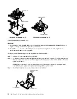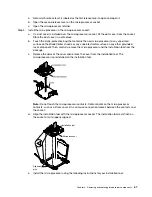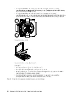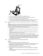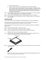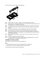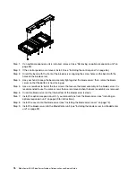
Step 6. Continue with step Step 3 “Open the microprocessor socket” on page 66.
Removing the system-board assembly
Use this information to remove the system-board assembly from the blade server. The system-board
assembly and must be replaced by a trained technician.
When you replace the system board, you will replace the system board and blade base as one assembly.
After replacement, you must either update the blade server with the latest firmware or restore the pre-
existing firmware that the customer provides on a diskette or CD image.
Note:
See “Blade server system-board layouts” on page 7 for more information on the locations of the
connectors, jumpers and LEDs on the system board.
To remove the system-board assembly, complete the following steps:
Step 1. Before you begin, read “Safety” on page iii, “Handling static-sensitive devices” on page 38, and
“Installation guidelines” on page 37.
Step 2. If the blade server is installed in a BladeCenter unit, remove it (see “Removing the blade server from
the BladeCenter unit” on page 39 for instructions).
Step 3. Carefully lay the blade server on a flat, static-protective surface.
Step 4. Remove the blade server cover (see “Removing the blade server cover” on page 72).
Step 5. If an optional expansion unit is installed, remove the expansion unit (see “Removing an optional
Step 6. Remove all of the installed components in the following list from the system-board assembly; then,
place them on a static-protective surface or install them on the new system-board assembly.
• Front bezel. See “Removing the bezel assembly” on page 74.
• Control panel. See “Removing the control panel” on page 55.
• DIMMs. See “Removing a memory module” on page 45.
• USB module. See “Removing a USB Flash key” on page 49.
• I/O expansion cards. See “Removing a CIOv-form-factor expansion card” on page 51,
“Removing a horizontal-compact-form-factor expansion card” on page 51, and “Removing a
10Gb interposer card” on page 52.
• Storage drives. See “Removing a hot-swap storage drive” on page 44.
• Microprocessors and heat sinks. See “Removing a microprocessor and heat sink” on page 61.
Step 7. If you are instructed to return the system-board assembly, follow all packaging instructions, and
use any packaging materials for shipping that are supplied to you.
Installing the system-board assembly
Use this information to install the system-board assembly in the blade server.
Important:
When you replace the system board, you must either update the server with the latest firmware or
restore the pre-existing firmware that the customer provides on a diskette or CD image. Make sure that you
have the latest firmware or a copy of the pre-existing firmware before you proceed. See “Updating the DMI/
SMBIOS data” on page 18 and “Updating firmware and device drivers” on page 23 for more information.
To install the system-board assembly, complete the following steps:
Step 1. Install all of the components in the following list that you removed from the old system-board
assembly onto the new system-board assembly.
.
Removing and replacing blade server components
71
Summary of Contents for BladeCenter HS23 1929
Page 1: ...BladeCenter HS23 Blade Server Problem Determination and Service Guide Machine Types 7875 1929 ...
Page 284: ...268 BladeCenter HS23 Blade ServerProblem Determination and Service Guide ...
Page 289: ...Taiwan BSMI RoHS declaration Appendix B Notices 273 ...
Page 290: ...274 BladeCenter HS23 Blade ServerProblem Determination and Service Guide ...
Page 296: ...280 BladeCenter HS23 Blade ServerProblem Determination and Service Guide ...
Page 297: ......
Page 298: ...Part Number 00KC215 Printed in China 1P P N 00KC215 ...
Page 299: ... 1P00KC215 ...

