2.
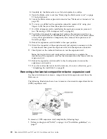
If the blade server is installed in a BladeCenter unit, remove it (see “Removing
the blade server from the BladeCenter unit” on page 20 for instructions).
3.
Carefully lay the blade server on a flat, static-protective surface.
4.
Open the blade server cover (see “Removing the blade server cover” on page
21 for instructions).
5.
Locate the CFFh expansion card. The CFFh expansion card is installed into the
blade expansion connector (see “Blade server connectors” on page 15).
6.
Rotate the expansion-card standoffs to the open position.
7.
Lift the release lever to disengage the CFFh expansion card from the expansion
connector on the system board.
8.
Use your fingers to hold the edge of the CFFh expansion card where it
connects to the blade expansion connector; then, lift the card vertically out of
the expansion connector.
Installing a CIOv-form-factor expansion card
Use these instructions to install a CIOv-form-factor expansion card in the blade
server.
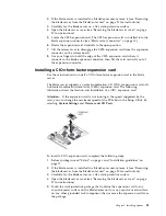
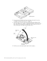
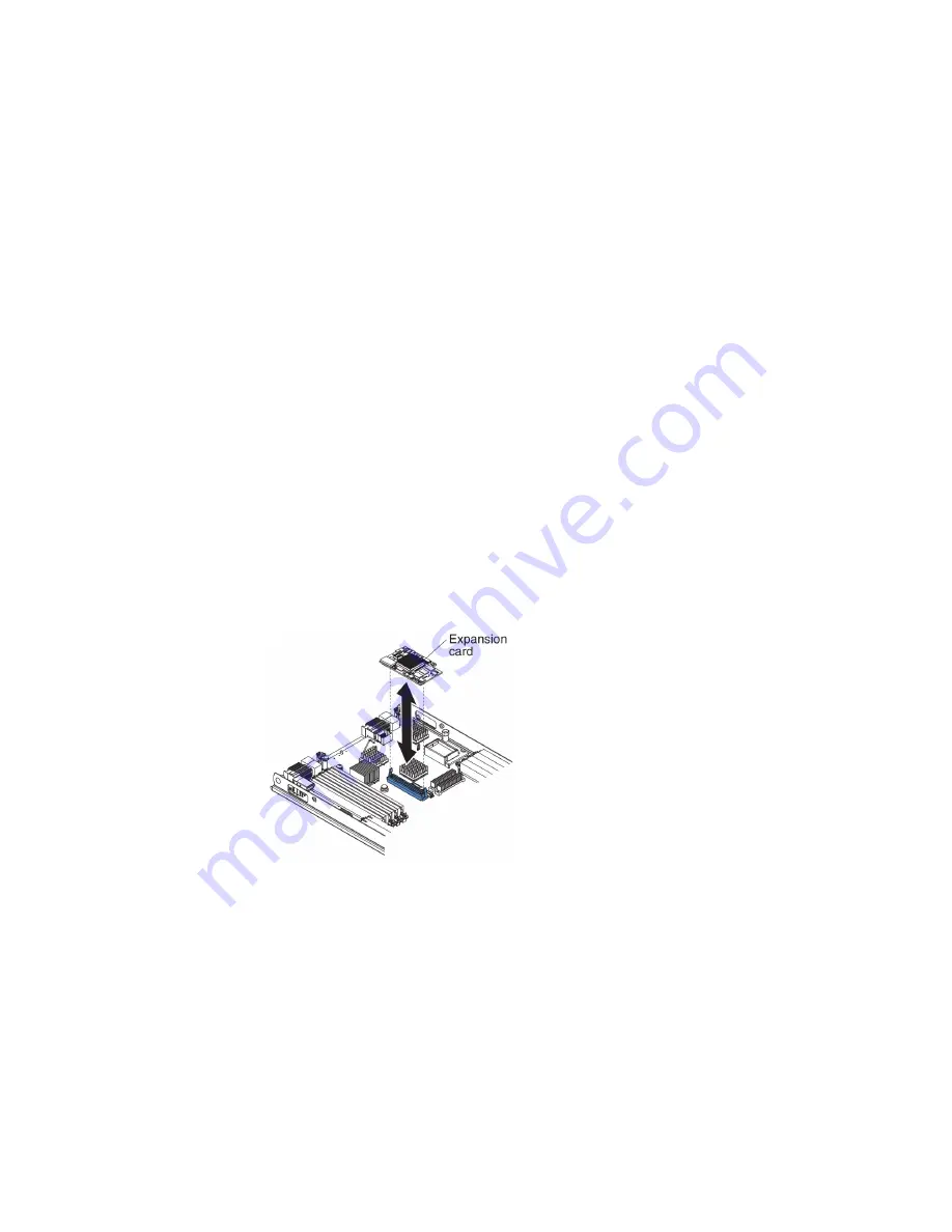
The blade server supports a vertical-combination-I/O (CIOv) expansion card and a
horizontal-combination-form-factor (CFFh) expansion card. The following
illustration shows the location and installation of a CIOv expansion card.
Attention:
If the expansion card is not running at the speed supported by the
card, you can change the maximum speed of the PCIe bus in the Setup Utility by
selecting System Settings and Devices and I/O Ports.
To install a CIOv expansion card, complete the following steps:
1.
Before you begin, read “Safety” on page v and “Installation guidelines” on
page 17.
2.
If the blade server is installed in a BladeCenter unit, remove it (see “Removing
the blade server from the BladeCenter unit” on page 20 for instructions).
3.
Carefully lay the blade server on a flat, static-protective surface.
4.
Open the blade server cover (see “Removing the blade server cover” on page
21 for instructions).
5.
Touch the static-protective package that contains the expansion card to any
unpainted metal surface on the BladeCenter unit or any unpainted metal surface
on any other grounded rack component; then, remove the expansion card from
the package.
Chapter 3. Installing options
41
Summary of Contents for BladeCenter HS23
Page 12: ...xii BladeCenter HS23 Types 7875 and 1929 Installation and User s Guide ...
Page 28: ...16 BladeCenter HS23 Types 7875 and 1929 Installation and User s Guide ...
Page 62: ...50 BladeCenter HS23 Types 7875 and 1929 Installation and User s Guide ...
Page 84: ...72 BladeCenter HS23 Types 7875 and 1929 Installation and User s Guide ...
Page 98: ...86 BladeCenter HS23 Types 7875 and 1929 Installation and User s Guide ...
Page 102: ...90 BladeCenter HS23 Types 7875 and 1929 Installation and User s Guide ...
Page 103: ......
Page 104: ...Part Number 00AK736 Printed in USA 1P P N 00AK736 1P00AK736 ...

