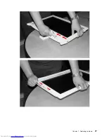
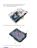
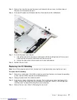
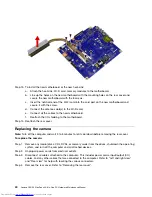
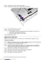


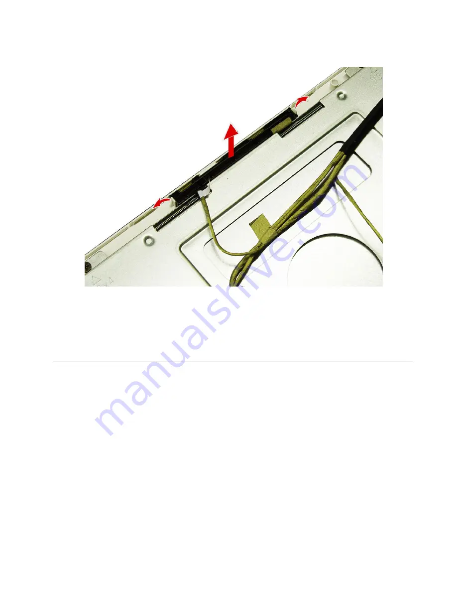
Step 5.
Pull the locking pins outward to release the camera module.
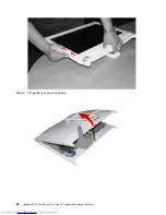
Step 6.
Disconnect the data cable from the connector on the camera module.
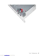
Step 7.
To install the new camera:
a.
Connect the data cable to the new camera.
b.
Slide the new camera into position and secure the camera with the two locking pins.
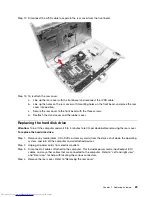
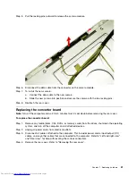
Step 8.
Reattach the rear cover.
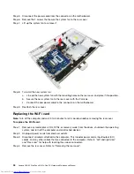
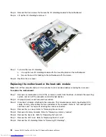
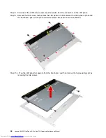
Replacing the converter board
Note:
Turn off the computer and wait 3 to 5 minutes to let it cool down before removing the rear cover.
To replace the converter board:
Step 1.
Remove any media (disks, CDs, DVDs, or memory cards) from the drives, shut down the operating
system, and turn off the computer and all attached devices.
Step 2.
Unplug all power cords from electrical outlets.
Step 3.
Disconnect all cables attached to the computer. This includes power cords, input/output (I/O)
cables, and any other cables that are connected to the computer. Refer to “Left and right view”
and “Rear view” for help with locating the various connectors.
Step 4.
Remove the rear cover. Refer to “Removing the rear cover”.
Chapter 7
.
Replacing hardware
41
Summary of Contents for C20-00
Page 1: ...Lenovo C20 00 Non Touch All In One PC Hardware Maintenance Manual Machine Types F0BB C20 00 ...
Page 2: ......
Page 3: ...Lenovo C20 00 Non Touch All In One PC Hardware Maintenance Manual Machine Types F0BB C20 00 ...
Page 6: ...iv Lenovo C20 00 Non Touch All In One PC Hardware Maintenance Manual ...
Page 8: ...2 Lenovo C20 00 Non Touch All In One PC Hardware Maintenance Manual ...
Page 16: ...10 Lenovo C20 00 Non Touch All In One PC Hardware Maintenance Manual ...
Page 18: ...12 Lenovo C20 00 Non Touch All In One PC Hardware Maintenance Manual ...
Page 24: ...18 Lenovo C20 00 Non Touch All In One PC Hardware Maintenance Manual ...
Page 33: ...Chapter 7 Replacing hardware 27 ...
Page 49: ...Chapter 7 Replacing hardware 43 ...
Page 52: ...46 Lenovo C20 00 Non Touch All In One PC Hardware Maintenance Manual ...
Page 60: ...54 Lenovo C20 00 Non Touch All In One PC Hardware Maintenance Manual ...