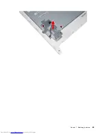


Step 11. To install the new LED panel module:
a.
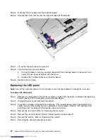
Attach the panel bracket to the LED panel with the two screws.
b.
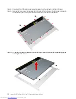
Line up the panel assembly with the front bezel, then place the panel into position.
c.
Secure the new panel to the front bezel with the four screws and pins.
d.
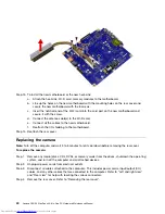
Attach the LVDS-camera and converter cables to the connectors on the new LED panel.
e.
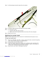
Attach the converter bracket to the front bezel.
f.
Attach the converter board to the bracket.
g.
Attach the camera to the new LED panel.
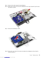
Step 12. Reattach the rear cover.
Chapter 7
.
Replacing hardware
45
Summary of Contents for C20-00
Page 1: ...Lenovo C20 00 Non Touch All In One PC Hardware Maintenance Manual Machine Types F0BB C20 00 ...
Page 2: ......
Page 3: ...Lenovo C20 00 Non Touch All In One PC Hardware Maintenance Manual Machine Types F0BB C20 00 ...
Page 6: ...iv Lenovo C20 00 Non Touch All In One PC Hardware Maintenance Manual ...
Page 8: ...2 Lenovo C20 00 Non Touch All In One PC Hardware Maintenance Manual ...
Page 16: ...10 Lenovo C20 00 Non Touch All In One PC Hardware Maintenance Manual ...
Page 18: ...12 Lenovo C20 00 Non Touch All In One PC Hardware Maintenance Manual ...
Page 24: ...18 Lenovo C20 00 Non Touch All In One PC Hardware Maintenance Manual ...
Page 33: ...Chapter 7 Replacing hardware 27 ...
Page 49: ...Chapter 7 Replacing hardware 43 ...
Page 52: ...46 Lenovo C20 00 Non Touch All In One PC Hardware Maintenance Manual ...
Page 60: ...54 Lenovo C20 00 Non Touch All In One PC Hardware Maintenance Manual ...


