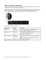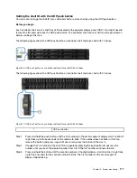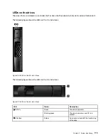
Seven-segment display overview
The DE2000/DE4000/DE6000 controllers have a two-digit, seven-segment display at the back, which shows
the following information.
Controller state
Seven-segment display
Functioning correctly
Tray ID
Not functioning correctly
Diagnostic codes to help identify errors
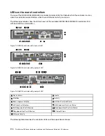
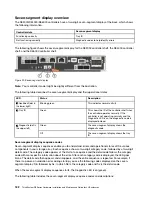
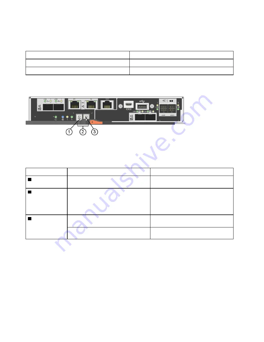
The following figure shows the seven-segment display for the DE2000 controller shelf, the DE4000 controller
shelf, and the DE6000 controller shelf.
Figure 22. Seven-segment display
Note:
Your controller model might be slightly different from the illustration.
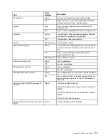
The following table describes the seven-segment display and their operational states.
LED
Status
Description
1
Heartbeat (dot in
the lower right)
Blinking green
This indicates normal activity.
2
Tray ID
Green
This shows the ID of the controller shelf when
the controller operates normally. If the
controller is not operating normally and the
Diagnostic LED is on, the diagnostic code is
displayed instead.
3
Diagnostic (dot in
the upper left)
Green
The seven-segment display shows the
diagnostic code.
Off
The seven-segment display shows the tray
ID.
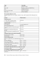
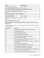
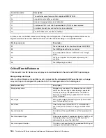
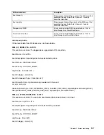
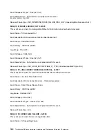
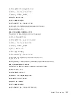
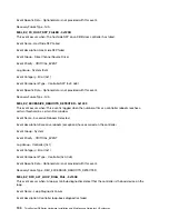
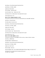
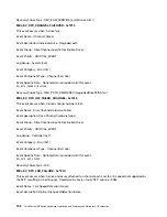
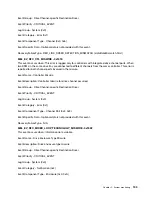
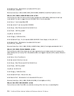
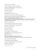
Seven-segment display sequence codes
Seven-segment display sequences enable you to understand errors and operational states of the various
components in your storage array. Each sequence shows a two-digit category code, followed by a two-digit
detail code. The category code appears at the start of a sequence and the detail code follows the category
code with more specific information about the error. After each category code is displayed, the LED goes
blank. The detail code then appears and disappears, and the entire sequence is repeated. For example, if
there is a power-on validation error during startup, you see the following codes displayed on the seven-
segment display: SE, followed by Sx, in which SE is the category code and Sx is the detail code.
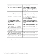
When the seven-segment display sequence starts, the Diagnostic LED is on (green).
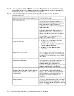
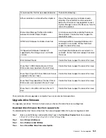
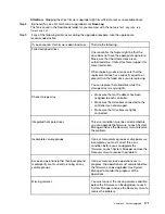
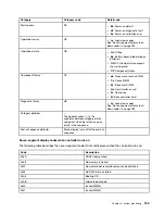
The following table includes the seven-segment display sequence codes and descriptions:
182
ThinkSystem DE Series Hardware Installation and Maintenance Guide for 2U Enclosures
Summary of Contents for DE120S
Page 96: ...90 ThinkSystem DE Series Hardware Installation and Maintenance Guide for 2U Enclosures ...
Page 282: ...276 ThinkSystem DE Series Hardware Installation and Maintenance Guide for 2U Enclosures ...
Page 284: ...278 ThinkSystem DE Series Hardware Installation and Maintenance Guide for 2U Enclosures ...
Page 291: ......
Page 292: ......

