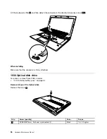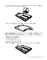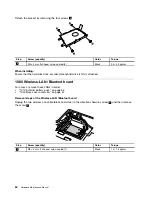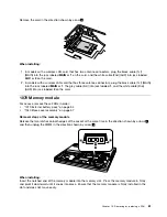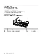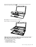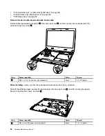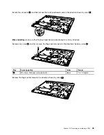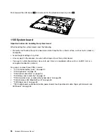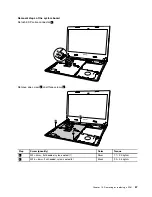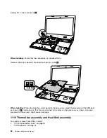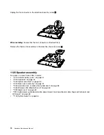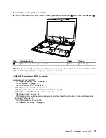
Insert a screwdriver into the screw hold and push the optical driver in the direction shown by arrow
2
. Pull
the optical drive out in the direction shown by arrow
3
.
b
c
Remove the ODD bezel
4
. Loosen two screws
5
and then detach the ODD bracket
6
.
d
e
f
e
Step
Screw (quantity)
Color
Torque
5
SCREW M2*3mm, flat-head, nylok-coated (2)
Black
1.0– 1.5 kgfcm
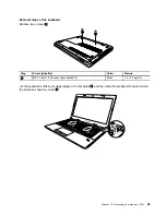
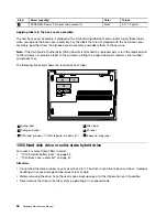
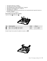
1040 Base cover assembly
For access, remove these FRUs:
•
“1010 External battery pack” on page 54
Removal steps of the base cover assembly
Remove the screws
1
that secure the base cover assembly. Remove the base cover assembly
2
.
b
a
a
b
57
Summary of Contents for E40-80
Page 1: ...Hardware Maintenance Manual Lenovo E40 80 ...
Page 4: ...ii Hardware Maintenance Manual ...
Page 6: ...iv Hardware Maintenance Manual ...
Page 11: ...DANGER DANGER DANGER DANGER DANGER Chapter 1 Safety information 5 ...
Page 12: ...6 Hardware Maintenance Manual ...
Page 13: ...PERIGO PERIGO PERIGO PERIGO Chapter 1 Safety information 7 ...
Page 14: ...PERIGO PERIGO PERIGO PERIGO DANGER 8 Hardware Maintenance Manual ...
Page 15: ...DANGER DANGER DANGER DANGER DANGER DANGER Chapter 1 Safety information 9 ...
Page 16: ...DANGER VORSICHT VORSICHT VORSICHT VORSICHT 10 Hardware Maintenance Manual ...
Page 17: ...VORSICHT VORSICHT VORSICHT VORSICHT Chapter 1 Safety information 11 ...
Page 18: ...12 Hardware Maintenance Manual ...
Page 19: ...Chapter 1 Safety information 13 ...
Page 20: ...14 Hardware Maintenance Manual ...
Page 21: ...Chapter 1 Safety information 15 ...
Page 22: ...16 Hardware Maintenance Manual ...
Page 23: ...Chapter 1 Safety information 17 ...
Page 24: ...18 Hardware Maintenance Manual ...
Page 30: ...24 Hardware Maintenance Manual ...
Page 34: ...28 Hardware Maintenance Manual ...
Page 36: ...30 Hardware Maintenance Manual ...
Page 38: ...32 Hardware Maintenance Manual ...
Page 56: ...50 Hardware Maintenance Manual ...
Page 84: ...78 Hardware Maintenance Manual ...
Page 89: ......
Page 90: ......

