48
Lenovo Edge 2 15 Hardware Maintenance Manual
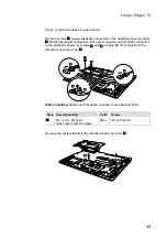
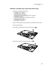
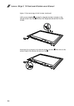
Figure 10. Removal steps of power assembly, touch pad module and IO board
(continued)
Remove the three screws
1
, then lift up and remove the touch pad module.
a
a
a
Step Screw (quantity)
Color Torque
1
M2 × 2 mm, flat-head,
nylok-coated (3) Touch pad module to
upper
Silver 1.85 +/- 0.15 kgf.cm


