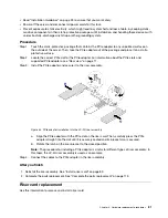
Figure 42. Removing the rear 4 x 3.5-inch drive backplane
After you finish
1. Do one of the following:
• If you are replacing the backplane, install a new backplane to the drive cage.
• If you are replacing the drive cage, install the backplane to a new drive cage.
2. If you are instructed to return the defective component, follow all packaging instructions and use any
packaging materials that are provided.
Install the rear 3.5-inch drive backplane
Use this information to install the rear 3.5-inch 4-bay drive backplane.
About this task
Attention:
• Read “Installation Guidelines” on page 25 to ensure that you work safely.
• Power off the server and disconnect all power cords for this task.
• Prevent exposure to static electricity, which might lead to system halt and loss of data, by keeping static-
sensitive components in their static-protective packages until installation, and handling these devices with
an electrostatic-discharge wrist strap or other grounding system.
Procedure
Step 1. Install the rear drive backplane.
a. Align the bottom of the backplane with the studs at the bottom of the drive cage, and lower the
backplane into the drive cage.
b. Push the top of the backplane forward until it clicks in place. Ensure that the holes in the
backplane pass through the pins on the drive cage, and the release latches secure the
backplane in position.
66
HR650X V2 User Guide
Summary of Contents for HR650X V2
Page 1: ...HR650X V2 User Guide Machine Types 7D4D ...
Page 8: ......
Page 14: ...6 HR650X V2 User Guide ...
Page 30: ...22 HR650X V2 User Guide ...
Page 122: ...114 HR650X V2 User Guide ...
Page 152: ...144 HR650X V2 User Guide ...
Page 176: ...168 HR650X V2 User Guide ...
Page 182: ...174 HR650X V2 User Guide ...
Page 186: ...178 HR650X V2 User Guide ...
Page 190: ...182 HR650X V2 User Guide ...
Page 191: ......
Page 192: ......


