1
2
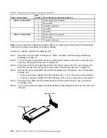
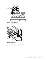
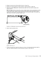
Cable cover
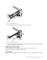
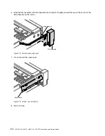
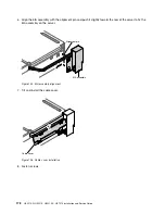
Figure 100. Cable cover removal
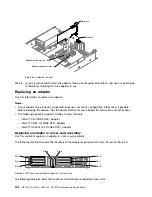
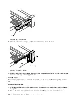
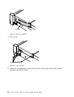
8. Grasp the EIA assembly and pull it slightly forward to remove it from the server.
EIA assembly
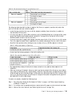
Figure 101. EIA assembly removal
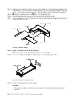
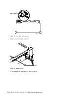
9. Position the EIA assembly as shown in the following illustration; then, remove the assembly out of
the server.
164
HX3510-G, HX5510, HX5510-C, HX7510 Installation and Service Guide
Summary of Contents for HX3510-G
Page 1: ...HX3510 G HX5510 HX5510 C HX7510 Installation and Service Guide Machine Type 8695 ...
Page 6: ...iv HX3510 G HX5510 HX5510 C HX7510 Installation and Service Guide ...
Page 62: ...50 HX3510 G HX5510 HX5510 C HX7510 Installation and Service Guide ...
Page 102: ...90 HX3510 G HX5510 HX5510 C HX7510 Installation and Service Guide ...
Page 112: ...100 HX3510 G HX5510 HX5510 C HX7510 Installation and Service Guide ...
Page 1222: ...1210 HX3510 G HX5510 HX5510 C HX7510 Installation and Service Guide ...
Page 1238: ...1226 HX3510 G HX5510 HX5510 C HX7510 Installation and Service Guide ...
Page 1239: ......
Page 1240: ......

