000000000000000
000000000000000
000000000000000
000000000000000
000000000000000
000000000000000
000000000000000
000000000000000
000000000000000
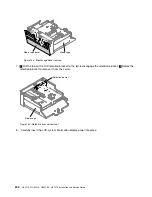
Operator information
panel assembly
Figure 160. Operator information panel installation
Step 5.
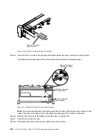
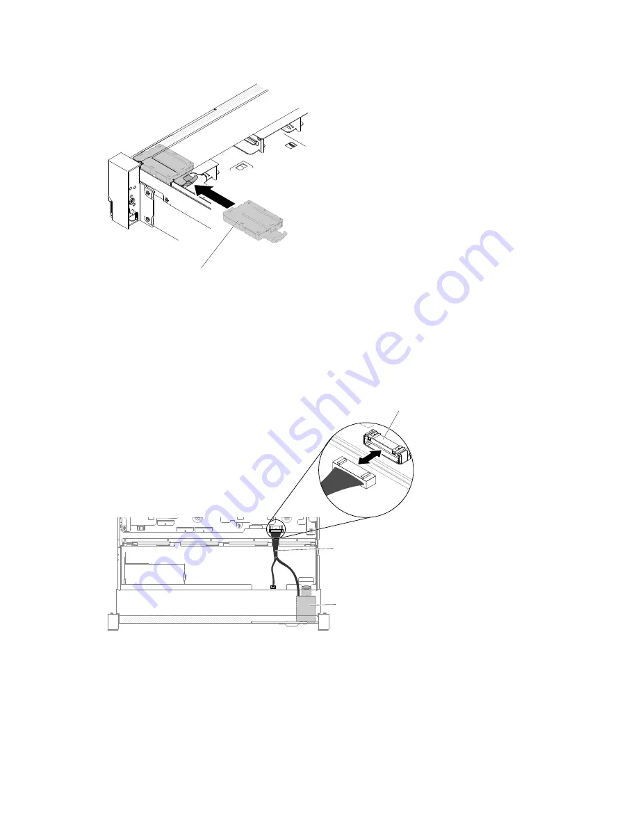
Inside the server, connect the operator information panel assembly cable to the system board.
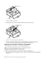
The following illustration shows the cable routing for the operator information panel.
0000000000000000000
Operator information /
LCD panel connector
Operator information /
LCD panel cable
Operator information
panel assembly
Figure 161. Operator information panel cable routing
Note:
To connect the operator information panel cable on the system board, press evenly on the
cable. Pressing on one side of the cable might cause damage to the cable or connector.
Step 6.
Replace the top cover (see “Replacing the top cover” on page 118).
Step 7.
Slide the server into the rack.
Step 8.
Reconnect the power cords and any cables that you removed.
204
HX3510-G, HX5510, HX5510-C, HX7510 Installation and Service Guide
Summary of Contents for HX3510-G
Page 1: ...HX3510 G HX5510 HX5510 C HX7510 Installation and Service Guide Machine Type 8695 ...
Page 6: ...iv HX3510 G HX5510 HX5510 C HX7510 Installation and Service Guide ...
Page 62: ...50 HX3510 G HX5510 HX5510 C HX7510 Installation and Service Guide ...
Page 102: ...90 HX3510 G HX5510 HX5510 C HX7510 Installation and Service Guide ...
Page 112: ...100 HX3510 G HX5510 HX5510 C HX7510 Installation and Service Guide ...
Page 1222: ...1210 HX3510 G HX5510 HX5510 C HX7510 Installation and Service Guide ...
Page 1238: ...1226 HX3510 G HX5510 HX5510 C HX7510 Installation and Service Guide ...
Page 1239: ......
Page 1240: ......

