E
5-
x6
xx
v
3
E
5-
x6
xx
v
4
E
5
-x
6
x
x
v
3
E
5
-x
6
x
x
v
4
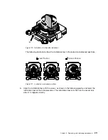
E5-x6xx v3
E5-x6xx v4
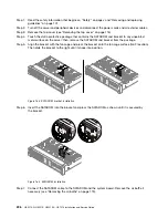
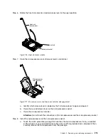
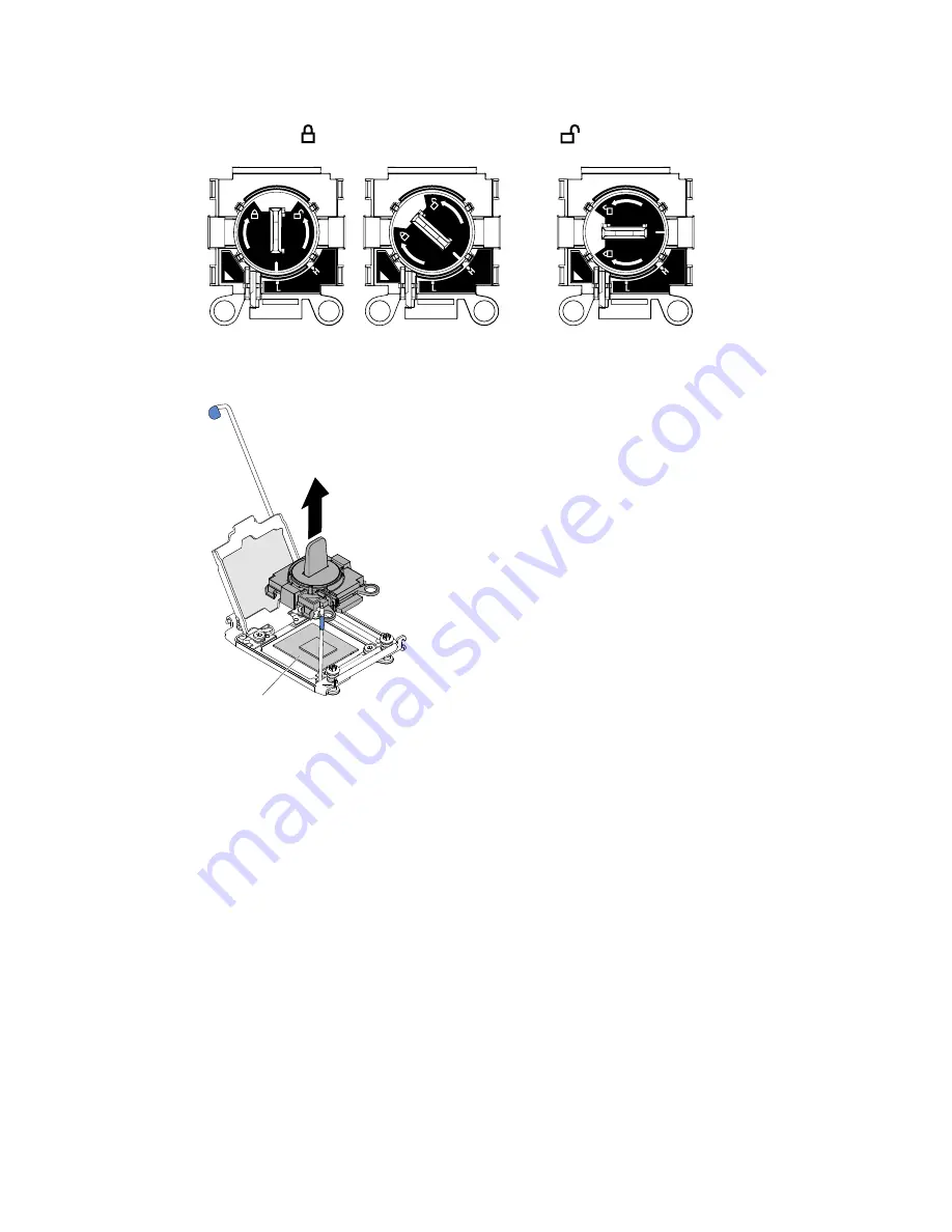
Lock Position
Unlock Position
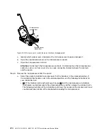
Figure 180. Installation tool
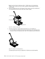
Microprocessor
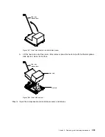
Figure 181. Installation tool removal
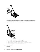
Attention:
• Do not press the microprocessor into the socket.
• Make sure that the microprocessor is oriented and aligned correctly in the socket before
you try to close the microprocessor retainer.
• Do not touch the thermal material on the bottom of the heat sink or on top of the
microprocessor. Touching the thermal material will contaminate it.
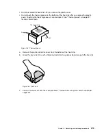
Step 9.
Remove the cover from the retainer bracket, if one is present. Store the cover in a safe place.
.
Removing, and replacing components
217
Summary of Contents for HX3510-G
Page 1: ...HX3510 G HX5510 HX5510 C HX7510 Installation and Service Guide Machine Type 8695 ...
Page 6: ...iv HX3510 G HX5510 HX5510 C HX7510 Installation and Service Guide ...
Page 62: ...50 HX3510 G HX5510 HX5510 C HX7510 Installation and Service Guide ...
Page 102: ...90 HX3510 G HX5510 HX5510 C HX7510 Installation and Service Guide ...
Page 112: ...100 HX3510 G HX5510 HX5510 C HX7510 Installation and Service Guide ...
Page 1222: ...1210 HX3510 G HX5510 HX5510 C HX7510 Installation and Service Guide ...
Page 1238: ...1226 HX3510 G HX5510 HX5510 C HX7510 Installation and Service Guide ...
Page 1239: ......
Page 1240: ......

