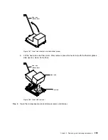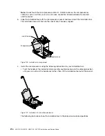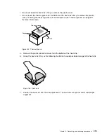
Retainer bracket tabs
Heat sink
release lever
Lock tab
Heat sink
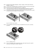
Figure 186. Heat sink installation
d.
Align and insert the front tab of the heat sink under the retainer bracket tabs.
e.
Align and place the heat sink on top of the microprocessor in the retention bracket, thermal
material side down.
f.
Press firmly on the heat sink.
g.
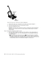
Rotate the heat sink retention module release lever to the closed position and hook it
underneath the lock tab.
Heat sink
release lever
Heat sink
Figure 187. Heat sink retention module release lever
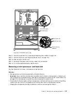
Step 12. Reinstall the air baffle (see “Replacing the air baffle” on page 120).
Step 13. Install the top cover (see “Replacing the top cover” on page 118).
220
HX3510-G, HX5510, HX5510-C, HX7510 Installation and Service Guide
Summary of Contents for HX3510-G
Page 1: ...HX3510 G HX5510 HX5510 C HX7510 Installation and Service Guide Machine Type 8695 ...
Page 6: ...iv HX3510 G HX5510 HX5510 C HX7510 Installation and Service Guide ...
Page 62: ...50 HX3510 G HX5510 HX5510 C HX7510 Installation and Service Guide ...
Page 102: ...90 HX3510 G HX5510 HX5510 C HX7510 Installation and Service Guide ...
Page 112: ...100 HX3510 G HX5510 HX5510 C HX7510 Installation and Service Guide ...
Page 1222: ...1210 HX3510 G HX5510 HX5510 C HX7510 Installation and Service Guide ...
Page 1238: ...1226 HX3510 G HX5510 HX5510 C HX7510 Installation and Service Guide ...
Page 1239: ......
Page 1240: ......

