00
00
00
00
0
0
0
0
000
000
000
000
000
000
0
0
0
00
00
00
00
00
00
00
00
00
00
00
00
00
00000
00000
00000
00000
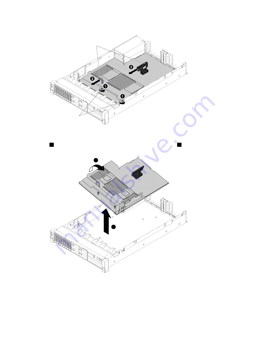
Thumb screws
System board handles
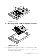
Figure 192. System board removal
Step 17.
1
Push the system board toward the broadside of the server and
2
lift the system board up.
00
00
00
00
0
0
0
0
000
000
000
000
000
000
0
0
0
00
00
00
00
00
00
00
00
00
00
00
00
00
00000
00000
00000
00000
1
2
Figure 193. System board removal
Step 18. If you are instructed to return the system board, follow all packaging instructions, and use any
packaging materials for shipping that are supplied to you.
Attention:
Make sure to place the socket covers for the microprocessor sockets on the system
board before returning the system board.
.
Removing, and replacing components
225
Summary of Contents for HX3510-G
Page 1: ...HX3510 G HX5510 HX5510 C HX7510 Installation and Service Guide Machine Type 8695 ...
Page 6: ...iv HX3510 G HX5510 HX5510 C HX7510 Installation and Service Guide ...
Page 62: ...50 HX3510 G HX5510 HX5510 C HX7510 Installation and Service Guide ...
Page 102: ...90 HX3510 G HX5510 HX5510 C HX7510 Installation and Service Guide ...
Page 112: ...100 HX3510 G HX5510 HX5510 C HX7510 Installation and Service Guide ...
Page 1222: ...1210 HX3510 G HX5510 HX5510 C HX7510 Installation and Service Guide ...
Page 1238: ...1226 HX3510 G HX5510 HX5510 C HX7510 Installation and Service Guide ...
Page 1239: ......
Page 1240: ......

