000000
000000
000000
000000
000000
000000
00
00
00
00
00
00
00
0
0
0
0
0
0
0
0
00
00
00
00
00
00
0000000
0000000
0000000
0000000
0000000
0000000
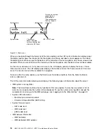
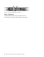
Ethernet
link LED
Ethernet
activity LED
AC power
LED (green)
DC power
LED (green)
Power-supply
error LED (yellow)
System power LED
System error LED
Locator batton / LED
000000
000000
000000
Figure 16. LEDs rear view
•
Ethernet activity LEDs:
When these LEDs are lit, they indicate that the server is transmitting to or
receiving signals from the Ethernet LAN that is connected to the Ethernet port.
•
Ethernet link LEDs:
When these LEDs are lit, they indicate that there is an active link connection on the
10BASE-T, 100BASE-TX, or 1000BASE-TX interface for the Ethernet port.
•
AC power LED:
Each hot-swap ac power supply has an ac power LED. When the ac power LED is
lit, it indicates that sufficient power is coming into the power supply through the power cord. During
typical operation, the ac power LED is lit. For any other combination of LEDs, see “AC power-supply
LEDs” on page 57.
•
DC power LED:
Each hot-swap ac power supply has a dc power LED. When the dc power LED is lit, it
indicates that the power supply is supplying adequate dc power to the system. During typical operation,
both the ac and dc power LEDs are lit.
•
Power-supply error LED:
When the power-supply error LED is lit, it indicates that the power supply
has failed.
Note:
Power supply 1 is the default/primary power supply. If power supply 1 fails, you must replace
the power supply immediately.
•
Power-on LED:
When this LED is lit and not flashing, it indicates that the server is turned on. The states
of the power-on LED are as follows:
Off:
Power is not present, or the power supply or the LED itself has failed.
Flashing rapidly (4 times per second):
The server is turned off and is not ready to be turned on. The
power-control button is disabled. This will last approximately 5 to 10 seconds.
Flashing slowly (once per second):
The server is turned off and is ready to be turned on. You can
press the power-control button to turn on the server.
Lit:
The server is turned on.
•
System-locator LED:
Use this LED to visually locate the server among other servers. You can use Lenovo
XClarity Administrator to light this LED remotely.
•
System-error LED:
When this LED is lit, it indicates that a system error has occurred. An LED on the LCD
system information display panel (if available) is also lit to help isolate the error.
PCI riser-card adapter expansion slot locations
The section shows the PCI expansion slot connector locations.
The Lenovo Converged HX Series server
21
Summary of Contents for HX3510-G
Page 1: ...HX3510 G HX5510 HX5510 C HX7510 Installation and Service Guide Machine Type 8695 ...
Page 6: ...iv HX3510 G HX5510 HX5510 C HX7510 Installation and Service Guide ...
Page 62: ...50 HX3510 G HX5510 HX5510 C HX7510 Installation and Service Guide ...
Page 102: ...90 HX3510 G HX5510 HX5510 C HX7510 Installation and Service Guide ...
Page 112: ...100 HX3510 G HX5510 HX5510 C HX7510 Installation and Service Guide ...
Page 1222: ...1210 HX3510 G HX5510 HX5510 C HX7510 Installation and Service Guide ...
Page 1238: ...1226 HX3510 G HX5510 HX5510 C HX7510 Installation and Service Guide ...
Page 1239: ......
Page 1240: ......

