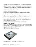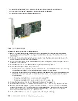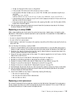
Replacing the SATADOM boot drive
Lenovo support may instruct you that the SATADOM boot drive needs to be replaced. This is a level 2 CRU
and should be performed by a trained Lenovo field representative.
To replace the SATADOM, perform the following steps:
1. Shut down the node by following the hypervisor specific Node Shutdown procedure described in the
Nutanix Hardware Replacement Documentation.
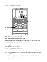
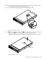
2. Remove the top cover as described in “Removing the top cover” on page 116.
3. Remove the SATADOM boot drive as described in “Removing the SATADOM” on page 205.
4. Replace the SATADOM boot drive as described in “Replacing the SATADOM” on page 205.
5. Replace the top cover as described in “Replacing the top cover” on page 118.
6. Return the node to the rack and reconnect the cables as necessary. Power on the node.
7. Verify that the boot drive has been successfully replaced by checking the following:
8. Stop the startup process at the main IMM menu screen to configure the boot SSD for the Lenovo
Converged HX Series appliances:
• Configure boot drive virtual drives
• Select virtual drive for booting
9. Use the Phoenix installer to reinstall the hypervisor and CVM by following the Imaging a Node procedure
in the appendix of the Nutanix Field Installation Guide.
Internal cable routing and connectors
This section provides information about routing the cables when you install some components in the server.
Note:
Disengage all latches, release tabs or locks on cable connectors when you disconnect all cables from
the system board. Failing to release them before removing the cables will damage the cable sockets on
the system board. The cable sockets on the system board are fragile. Any damage to the cable sockets
may require replacing the system board.
General cable routing connections
Cabling VGA power connector
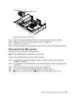
The internal routing and connectors for the front USB and video cables.
The following illustration shows the internal routing and connectors for the video graphic adapter (VGA)
power cables:
.
Removing, and replacing components
111
Summary of Contents for HX3510-G
Page 1: ...HX3510 G HX5510 HX5510 C HX7510 Installation and Service Guide Machine Type 8695 ...
Page 6: ...iv HX3510 G HX5510 HX5510 C HX7510 Installation and Service Guide ...
Page 62: ...50 HX3510 G HX5510 HX5510 C HX7510 Installation and Service Guide ...
Page 102: ...90 HX3510 G HX5510 HX5510 C HX7510 Installation and Service Guide ...
Page 112: ...100 HX3510 G HX5510 HX5510 C HX7510 Installation and Service Guide ...
Page 1222: ...1210 HX3510 G HX5510 HX5510 C HX7510 Installation and Service Guide ...
Page 1238: ...1226 HX3510 G HX5510 HX5510 C HX7510 Installation and Service Guide ...
Page 1239: ......
Page 1240: ......

