00
00
00
00
00
0
0
0
0
0
0
0000
0000
0000
0000
0000
0000
0000
0000
0000
0000
0
0
0
0
00
00
00
00
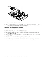
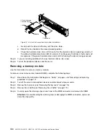
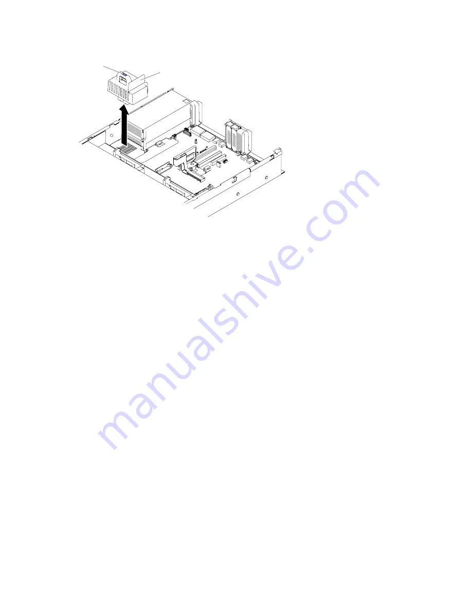
Power paddle assembly
Handle
Figure 49. Power paddle module removal
Step 6.
If you are instructed to return the power paddle module, follow all packaging instructions, and use
any packaging materials for shipping that are supplied to you.
Replacing the power paddle module
Use this information to install the power paddle module.
To install the power paddle module, complete the following steps:
Step 1.
Read the safety information that begins on “Safety” on page v and “Removing and replacing
guidelines” on page 101.
Step 2.
Turn off the server and peripheral devices and disconnect the power cords and all external cables,
if necessary.
Step 3.
Remove the top cover (see “Removing the top cover” on page 116).
Step 4.
Grasp the handle and align the power paddle module with the connector on the system board.
Push the power paddle module to the system board and make sure it is firmly seated.
122
HX3510-G, HX5510, HX5510-C, HX7510 Installation and Service Guide
Summary of Contents for HX3510-G
Page 1: ...HX3510 G HX5510 HX5510 C HX7510 Installation and Service Guide Machine Type 8695 ...
Page 6: ...iv HX3510 G HX5510 HX5510 C HX7510 Installation and Service Guide ...
Page 62: ...50 HX3510 G HX5510 HX5510 C HX7510 Installation and Service Guide ...
Page 102: ...90 HX3510 G HX5510 HX5510 C HX7510 Installation and Service Guide ...
Page 112: ...100 HX3510 G HX5510 HX5510 C HX7510 Installation and Service Guide ...
Page 1222: ...1210 HX3510 G HX5510 HX5510 C HX7510 Installation and Service Guide ...
Page 1238: ...1226 HX3510 G HX5510 HX5510 C HX7510 Installation and Service Guide ...
Page 1239: ......
Page 1240: ......

