00
00
00
00
00
0
0
0
0
0
0
0000
0000
0000
0000
0000
0000
0000
0000
0000
0000
0
0
0
0
00
00
00
00
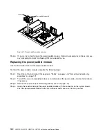
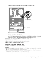
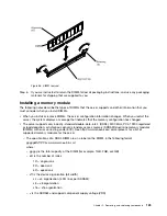
Power paddle assembly
Handle
Figure 50. Power paddle module installation
Step 5.
Replacing the power supplies (See “Replacing a hot-swap ac power supply” on page 181).
Step 6.
Replacing the top cover (see “Replacing the top cover” on page 118).
Step 7.
Slide the server into the rack.
Step 8.
Reconnect the power cords and all external cables, and turn on the server and peripheral devices.
Removing the front USB assembly
Use this information to remove the front USB assembly.
Note:
The front USB assembly is available only on some models.
To remove the front USB assembly, complete the following steps.
Step 1.
Read the safety information that begins on “Safety” on page v and “Removing and replacing
guidelines” on page 101.
Step 2.
Turn off the server and peripheral devices and disconnect the power cords and all external cables,
if necessary.
Step 3.
Remove the top cover (see “Removing the top cover” on page 116).
Step 4.
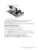
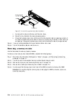
Disconnect the cable on the front USB assembly from the system board.
Step 5.
1
Pull up the release latch slightly and
2
slide the front USB assembly out of the server.
.
Removing, and replacing components
123
Summary of Contents for HX3510-G
Page 1: ...HX3510 G HX5510 HX5510 C HX7510 Installation and Service Guide Machine Type 8695 ...
Page 6: ...iv HX3510 G HX5510 HX5510 C HX7510 Installation and Service Guide ...
Page 62: ...50 HX3510 G HX5510 HX5510 C HX7510 Installation and Service Guide ...
Page 102: ...90 HX3510 G HX5510 HX5510 C HX7510 Installation and Service Guide ...
Page 112: ...100 HX3510 G HX5510 HX5510 C HX7510 Installation and Service Guide ...
Page 1222: ...1210 HX3510 G HX5510 HX5510 C HX7510 Installation and Service Guide ...
Page 1238: ...1226 HX3510 G HX5510 HX5510 C HX7510 Installation and Service Guide ...
Page 1239: ......
Page 1240: ......

