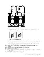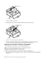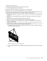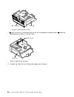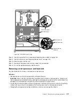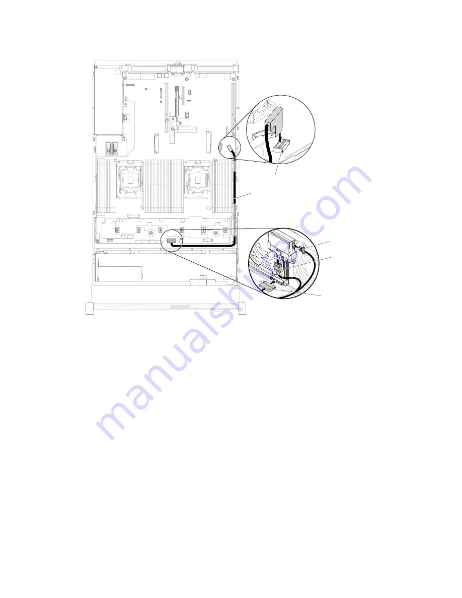
SATA 0 connector
SATADOM cable
Power connector
Signal connector
Optical disk drive
connector
0000000
0000000
0000000
0000000
0000000
0000000
0000000
0000000
0000000
0000000
0000000
0000000
0000000
0000000
0000000
Figure 165. SATADOM cable routing
Step 8.
Install the air baffle if it is removed (see “Replacing the air baffle” on page 120).
Step 9.
Install the top cover (see “Replacing the top cover” on page 118).
Step 10. Slide the server into the rack.
Step 11. Reconnect the power cords and any cables that you removed.
Step 12. Turn on the peripheral devices and the server.
Removing a microprocessor and heat sink
Use this information to remove a microprocessor and heat sink.
Attention:
• Microprocessors are to be removed only by trained technicians.
Important:
Always use the microprocessor installation tool to remove a microprocessor. Failing to use
the microprocessor installation tool may damage the microprocessor sockets on the system board. Any
damage to the microprocessor sockets may require replacing the system board.
• Do not allow the thermal grease on the microprocessor and heat sink to come in contact with anything.
Contact with any surface can compromise the thermal grease and the microprocessor socket.
• Dropping the microprocessor during installation or removal can damage the contacts.
.
Removing, and replacing components
207
Summary of Contents for HX3510-G
Page 1: ...HX3510 G HX5510 HX5510 C HX7510 Installation and Service Guide Machine Type 8695 ...
Page 6: ...iv HX3510 G HX5510 HX5510 C HX7510 Installation and Service Guide ...
Page 62: ...50 HX3510 G HX5510 HX5510 C HX7510 Installation and Service Guide ...
Page 102: ...90 HX3510 G HX5510 HX5510 C HX7510 Installation and Service Guide ...
Page 112: ...100 HX3510 G HX5510 HX5510 C HX7510 Installation and Service Guide ...
Page 1222: ...1210 HX3510 G HX5510 HX5510 C HX7510 Installation and Service Guide ...
Page 1238: ...1226 HX3510 G HX5510 HX5510 C HX7510 Installation and Service Guide ...
Page 1239: ......
Page 1240: ......

