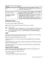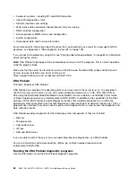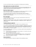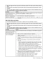
Step 1.
Is the server part of a cluster?
•
No:
Go to 2.
•
Yes:
Shut down all failing servers that are related to the cluster. Go to 2.
Step 2.
Complete the following steps:
a.
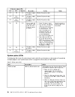
Check the power supply LEDs (see “Power-supply LEDs” on page 57).
b.
Turn off the server and all external devices.
c.
Check all internal and external devices for compatibility at http://www.lenovo.com/
serverproven/.
d.
Check all cables and power cords.
e.
Set all display controls to the middle positions.
f.
Turn on all external devices.
g.
Turn on the server. If the server does not start, see “Troubleshooting by symptom” on page 64.
h.
Check the system-error LED on the operator information panel. If it is lit, check the LCD system
information display panel (if available, see “LCD system information display panel” on page 16).
i.
Check for the following results:
• Successful completion of POST (see “POST” on page 61 for more information)
• Successful completion of startup, which is indicated by a readable display of the
operating-system desktop
Step 3.
Is there a readable image on the monitor screen?
•
No:
Find the failure symptom in “Troubleshooting by symptom” on page 64; if necessary, see
“Solving undetermined problems” on page 84.
•
Yes:
Run DSA (see “Running the DSA Preboot diagnostic programs” on page 62).
– If DSA reports an error, follow the instructions in Appendix C “DSA diagnostic test results”
– If DSA does not report an error but you still suspect a problem, see “Solving undetermined
Diagnostic tools
The section introduces available tools to help you diagnose and solve hardware-related problems.
•
LCD system information display panel (available on some models)
Use LCD system information display panel to diagnose system errors quickly.
•
Event logs
The event logs list the error codes and messages that are generated when an error is detected for the
subsystems IMM2, POST, DSA, and the server baseboard management controller. See “Event logs” on
page 59 for more information.
•
Integrated management module II (IMM2)
The IMM2 combines service processor functions, video controller, and remote presence and blue-screen
capture features in a single chip. The IMM provides advanced service-processor control, monitoring,
and alerting function. If an environmental condition exceeds a threshold or if a system component fails,
the IMM lights LEDs to help you diagnose the problem, records the error in the IMM event log, and
alerts you to the problem. Optionally, the IMM also provides a virtual presence capability for remote
server management capabilities. The IMM provides remote server management through the following
industry-standard interfaces:
55
Summary of Contents for HX3510-G
Page 1: ...HX3510 G HX5510 HX5510 C HX7510 Installation and Service Guide Machine Type 8695 ...
Page 6: ...iv HX3510 G HX5510 HX5510 C HX7510 Installation and Service Guide ...
Page 62: ...50 HX3510 G HX5510 HX5510 C HX7510 Installation and Service Guide ...
Page 102: ...90 HX3510 G HX5510 HX5510 C HX7510 Installation and Service Guide ...
Page 112: ...100 HX3510 G HX5510 HX5510 C HX7510 Installation and Service Guide ...
Page 1222: ...1210 HX3510 G HX5510 HX5510 C HX7510 Installation and Service Guide ...
Page 1238: ...1226 HX3510 G HX5510 HX5510 C HX7510 Installation and Service Guide ...
Page 1239: ......
Page 1240: ......


