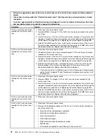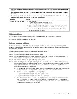
• Follow the suggested actions in the order in which they are listed in the Action column until the problem is
solved.
• If an action step is preceded by “(Trained technician only),” that step must be performed only by a trained
technician.
• Go to the support website at http://www.lenovo.com/support to check for technical information, hints, tips,
and new device drivers or to submit a request for information.
Symptom
Action
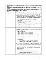
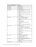
3. Return the removed DIMMs, one at a time, to their original connectors, restarting
the server after each DIMM, until a DIMM fails. Replace each failing DIMM
with an identical known good DIMM, restarting the server after each DIMM
replacement. Repeat step 3 until you have tested all removed DIMMs.
4. Replace the highest-numbered DIMM of those identified; then, restart the
server. Repeat as necessary.
5. Reverse the DIMMs between the channels (of the same microprocessor), and
then restart the server. If the problem is related to a DIMM, replace the failing
DIMM.
6. (Trained technician only) Install the failing DIMM into a DIMM connector
for microprocessor 2 (if installed) to verify that the problem is not the
microprocessor or the DIMM connector.
7. (Trained technician only) Replace the system board.
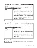
Microprocessor problems
Use the troubleshooting tables to find solutions to problems that have identifiable symptoms.
• Follow the suggested actions in the order in which they are listed in the Action column until the problem is
solved.
• If an action step is preceded by “(Trained technician only),” that step must be performed only by a trained
technician.
• Go to the support website at http://www.lenovo.com/support to check for technical information, hints, tips,
and new device drivers or to submit a request for information.
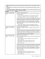
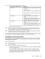
Symptom
Action
The server goes directly to the
POST Event Viewer when it is
turned on.
1. Correct any errors that are indicated by the LCD system information display
panel (if available).
2. Make sure that the server supports all the microprocessors and that the
microprocessors match in speed and cache size. To view the microprocessor
information, run the Setup Utility and select
System Information
➙
System
Summary
➙
Processor Details
.
3. (Trained technician only) Make sure that microprocessor 1 is seated correctly.
4. (Trained technician only) Remove microprocessor 2 and restart the server.
5. Replace the following components one at a time, in the order shown, restarting
the server each time:
a. (Trained technician only) Microprocessor
b. (Trained technician only) System board
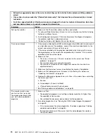
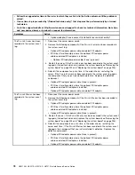
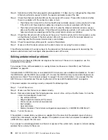
Monitor and video problems
Some monitors have their own self-tests. If you suspect a problem with your monitor, see the documentation
that comes with the monitor for instructions for testing and adjusting the monitor. If you cannot diagnose
the problem, call for service.
69
Summary of Contents for HX3510-G
Page 1: ...HX3510 G HX5510 HX5510 C HX7510 Installation and Service Guide Machine Type 8695 ...
Page 6: ...iv HX3510 G HX5510 HX5510 C HX7510 Installation and Service Guide ...
Page 62: ...50 HX3510 G HX5510 HX5510 C HX7510 Installation and Service Guide ...
Page 102: ...90 HX3510 G HX5510 HX5510 C HX7510 Installation and Service Guide ...
Page 112: ...100 HX3510 G HX5510 HX5510 C HX7510 Installation and Service Guide ...
Page 1222: ...1210 HX3510 G HX5510 HX5510 C HX7510 Installation and Service Guide ...
Page 1238: ...1226 HX3510 G HX5510 HX5510 C HX7510 Installation and Service Guide ...
Page 1239: ......
Page 1240: ......


