• Adapters and attachments, in the same locations
• Address jumpers, terminators, and cabling
• Software versions and levels
• Diagnostic program type and version level
• Configuration option settings
• Operating-system control-file setup
See Appendix D “Getting help and technical assistance” on page 1207 for information about calling Lenovo
for service.
Recovering the server firmware (UEFI update failure)
Use this information to recover the server firmware.
Important:
Some cluster solutions require specific code levels or coordinated code updates. If the device
is part of a cluster solution, verify that the latest level of code is supported for the cluster solution before
you update the code.
If the server firmware has become corrupted, such as from a power failure during an update, you can
recover the server firmware in the following way:
•
In-band method:
Recover server firmware, using either the boot block jumper (Automated Boot
Recovery) and a server Firmware Update Package Service Pack.
•
Out-of-band method:
Use the IMM web interface to update the firmware, using the latest server
firmware update package.
Note:
You can obtain a server update package from one of the following sources:
• Download the server firmware update from the World Wide Web.
• Contact your service representative.
To download the server firmware update package from the World Wide Web, go to
http://www.lenovo.com/support.
The flash memory of the server consists of a primary bank and a back up bank. You must maintain a
bootable UEFI firmware image in the back up bank. If the server firmware in the primary bank becomes
corrupted, you can either manually boot the back up bank with the UEFI boot backup jumper (J15), or in the
case of image corruption, this will occur automatically with the Automated Boot Recovery function.
In-band manual recovery method
This section details the in-band manual recovery method.
To recover the server firmware and restore the server operation to the primary bank, complete the following
steps:
Step 1.
Read the safety information that begins on “Safety” on page v and “Removing and replacing
guidelines” on page 101.
Step 2.
Turn off the server, and disconnect all power cords and external cables.
Step 3.
Remove the cover (see “Removing the top cover” on page 116).
Step 4.
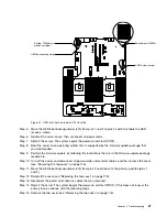
Locate the UEFI boot backup jumper (J15) on the system board.
86
HX3510-G, HX5510, HX5510-C, HX7510 Installation and Service Guide
Summary of Contents for HX3510-G
Page 1: ...HX3510 G HX5510 HX5510 C HX7510 Installation and Service Guide Machine Type 8695 ...
Page 6: ...iv HX3510 G HX5510 HX5510 C HX7510 Installation and Service Guide ...
Page 62: ...50 HX3510 G HX5510 HX5510 C HX7510 Installation and Service Guide ...
Page 102: ...90 HX3510 G HX5510 HX5510 C HX7510 Installation and Service Guide ...
Page 112: ...100 HX3510 G HX5510 HX5510 C HX7510 Installation and Service Guide ...
Page 1222: ...1210 HX3510 G HX5510 HX5510 C HX7510 Installation and Service Guide ...
Page 1238: ...1226 HX3510 G HX5510 HX5510 C HX7510 Installation and Service Guide ...
Page 1239: ......
Page 1240: ......


