background image

IdeaCentre A540-24ICB and A540-24API  
Hardware Maintenance Manual

Summary of Contents for IdeaCentre A540-24API

Page 1: ...IdeaCentre A540 24ICB and A540 24API Hardware Maintenance Manual ...

Page 2: ...Lenovo 2019 LIMITED AND RESTRICTED RIGHTS NOTICE If data or software is delivered pursuant to a General Services Administration GSA contract use reproduction or disclosure is subject to restrictions set forth in Contract No GS 35F 05925 ...

Page 3: ...hapter 5 Troubleshooting and recovery 41 Basic procedure for resolving computer problems 41 Troubleshooting 41 Startup problems 42 Screen problems 43 Audio problems 44 Network problems 45 Performance problems 47 Storage drive problems 48 CD or DVD problems 48 Serial connector problems 49 Software problems 49 Recovery 49 Restore system files and settings to an earlier point 50 Restore your files fr...

Page 4: ...Chapter 7 Notices and trademarks 121 ii IdeaCentre A540 24ICB and A540 24API Hardware Maintenance Manual ...

Page 5: ...s to troubleshoot problems Important This manual is intended only for trained service technicians who are familiar with IdeaCentre computers Use this manual along with the advanced diagnostic tests to troubleshoot problems effectively Before servicing a IdeaCentre computer be sure to read and understand Chapter 2 Important service information on page 27 Copyright Lenovo 2019 iii ...

Page 6: ...iv IdeaCentre A540 24ICB and A540 24API Hardware Maintenance Manual ...

Page 7: ... Do not wear loose clothing that can be trapped in the moving parts of a machine Ensure that your sleeves are fastened or rolled up above your elbows If your hair is long fasten it Insert the ends of your necktie or scarf inside clothing or fasten it with a nonconductive clip approximately 8 centimeters 3 inches from the end Do not wear jewelry chains metal frame eyeglasses or metal fasteners for ...

Page 8: ...you need to work on a machine that has exposed electrical circuits observe the following precautions Ensure that another person familiar with the power off controls is near you Remember Another person must be there to switch off the power if necessary Use only one hand when working with powered on electrical equipment keep the other hand in your pocket or behind your back Remember There must be a ...

Page 9: ...se conditions and the safety hazards they present Electrical hazards especially primary power primary voltage on the frame can cause serious or fatal electrical shock Explosive hazards such as a damaged CRT cathode ray tube face or bulging capacitor Mechanical hazards such as loose or missing hardware The guide consists of a series of steps presented in a checklist Begin the checks with the power ...

Page 10: ...ins a charge even when you are wearing a wrist strap Use the black side of a grounded work mat to provide a static free work surface The mat is especially useful when handling ESD sensitive devices Select a grounding system such as those listed below to provide protection that meets the specific service requirement Note The use of a grounding system is desirable but not required to protect against...

Page 11: ...ct and disconnect cables as described in the following tables when installing moving or opening covers on this product or attached devices To Connect To Disconnect 1 Turn everything OFF 2 First attach all cables to devices 3 Attach signal cables to connectors 4 Attach power cords to outlet 5 Turn device ON 1 Turn everything OFF 2 First remove power cords from outlet 3 Remove signal cables from con...

Page 12: ... an embedded Class 3A or Class 3B laser diode Note the following Laser radiation when open Do not stare into the beam do not view directly with optical instruments and avoid direct exposure to the beam 18 kg 37 lb 32 kg 70 5 lb 55 kg 121 2 lb CAUTION Use safe practices when lifting CAUTION The power control button on the device and the power switch on the power supply do not turn off the electrica...

Page 13: ...Chapter 1 Important safety information 7 ...

Page 14: ... 18 kg 37 lb 32 kg 70 5 lb 55 kg 121 2 lb 1 2 8 IdeaCentre A540 24ICB and A540 24API Hardware Maintenance Manual ...

Page 15: ... os cabos conforme descrito na tabela apresentada a seguir ao instalar mover ou abrir tampas deste produto ou de dispositivos conectados Para Conectar Para Desconectar 1 DESLIGUE Tudo 2 Primeiramente conecte todos os cabos aos dispositivos 3 Conecte os cabos de sinal aos conectores 4 Conecte os cabos de alimentação às tomadas 5 LIGUE os dispositivos 1 DESLIGUE Tudo 2 Primeiramente remova os cabos ...

Page 16: ...r integrado da Classe 3A ou da Classe 3B Observe o seguinte Radiação a laser quando aberto Não olhe diretamente para o feixe a olho nu ou com instrumentos ópticos e evite exposição direta ao feixe 18 kg 37 lb 32 kg 70 5 lb 55 kg 121 2 lb CUIDADO Utilize procedimentos de segurança para levantar equipamentos CUIDADO O botão de controle de alimentação do dispositivo e o botão para ligar desligar da f...

Page 17: ...Chapter 1 Important safety information 11 ...

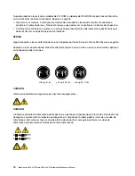
Page 18: ...1 2 12 IdeaCentre A540 24ICB and A540 24API Hardware Maintenance Manual ...

Page 19: ...Chapter 1 Important safety information 13 ...

Page 20: ...e seule main pour connecter ou déconnecter les câbles d interface Ne mettez jamais un équipement sous tension en cas d incendie ou d inondation ou en présence de dommages matériels Avant de retirer les carters de l unité mettez celle ci hors tension et déconnectez ses cordons d alimentation ainsi que les câbles qui la relient aux réseaux aux systèmes de télécommunication et aux modems sauf instruc...

Page 21: ...ropriée Ne pas la jeter à l eau l exposer à des températures supérieures à 100 C chercher à la réparer ou à la démonter Ne pas mettre la pile à la poubelle Pour la mise au rebut se reporter à la réglementation en vigueur ATTENTION Si des produits à laser tels que des unités de CD ROM de DVD ROM des unités à fibres optiques ou des émetteurs sont installés prenez connaissance des informations suivan...

Page 22: ...s Sicherheitsgründen Bei Gewitter an diesem Gerät keine Kabel anschließen oder lösen Ferner keine Installations Wartungs oder Rekonfigurationsarbeiten durchführen Gerät nur an eine Schutzkontaktsteckdose mit ordnungsgemäß geerdetem Schutzkontakt anschließen Alle angeschlossenen Geräte ebenfalls an Schutzkontaktsteckdosen mit ordnungsgemäß geerdetem Schutzkontakt anschließen Die Signalkabel nach Mö...

Page 23: ...atterie nur durch eine Batterie mit der Teilenummer 45C1566 oder eine gleichwertige vom Hersteller empfohlene Batterie ersetzen Enthält das System ein Modul mit einer Lithiumbatterie dieses nur durch ein Modul desselben Typs und von demselben Hersteller ersetzen Die Batterie enthält Lithium und kann bei unsachgemäßer Verwendung Handhabung oder Entsorgung explodieren Die Batterie nicht mit Wasser i...

Page 24: ...hine beachten ACHTUNG Mit dem Netzschalter an der Einheit und am Netzteil wird die Stromversorgung für die Einheit nicht unterbrochen Die Einheit kann auch mit mehreren Netzkabeln ausgestattet sein Um die Stromversorgung für die Einheit vollständig zu unterbrechen müssen alle zum Gerät führenden Netzkabel vom Netz getrennt werden 1 2 18 IdeaCentre A540 24ICB and A540 24API Hardware Maintenance Man...

Page 25: ...Chapter 1 Important safety information 19 ...

Page 26: ...rrente elettrica proveniente dai cavi di alimentazione del telefono e di comunicazione può essere pericolosa Per evitare il rischio di scosse elettriche 20 IdeaCentre A540 24ICB and A540 24API Hardware Maintenance Manual ...

Page 27: ...chiature 2 Innanzitutto collegare tutti i cavi alle unità 3 Collegare i cavi di segnale ai connettori 4 Collegare i cavi di alimentazione alla presa 5 Accendere l unità 1 SPEGNERE le apparecchiature 2 Innanzitutto rimuovere i cavi di alimentazione dalla presa 3 Rimuovere i cavi di segnale dai connettori 4 Rimuovere tutti i cavi dalle unità ATTENZIONE Quando si sostituisce la batteria al litio util...

Page 28: ...ndo l unità vengono emesse radiazioni laser Non fissare il fascio non guardarlo direttamente con strumenti ottici ed evitare l esposizione al fascio 18 kg 32 kg 55 kg ATTENZIONE Prestare attenzione nel sollevare l apparecchiatura ATTENZIONE Il pulsante di controllo dell alimentazione presente sull unità e l interruttore dell alimentatore non disattivano l alimentazione corrente fornita all unità E...

Page 29: ...Chapter 1 Important safety information 23 ...

Page 30: ...miento o reconfiguración de este producto durante una tormenta eléctrica Conecte todos los cables de alimentación a tomas de corriente debidamente cableadas y conectadas a tierra Cualquier equipo que se conecte a este producto también debe conectarse a tomas de corriente debidamente cableadas Siempre que sea posible utilice una sola mano para conectar o desconectar los cables de señal 24 IdeaCentr...

Page 31: ...ispositivos PRECAUCIÓN Cuando sustituya una batería de litio utilice solamente una batería número de pieza 45C1566 u otra de tipo equivalente recomendada por el fabricante Si su sistema dispone de un módulo que contiene una batería de litio reemplácelo sólo con el mismo tipo de módulo del mismo fabricante La batería contiene litio y puede explotar si no se utiliza manipula o desecha correctamente ...

Page 32: ...mientos seguros al levantar el equipo PRECAUCIÓN El botón de control de alimentación del dispositivo y el interruptor de alimentación de la fuente de alimentación no desconectan la corriente eléctrica suministrada al dispositivo Además el dispositivo podría tener más de un cable de alimentación Para suprimir toda la corriente eléctrica del dispositivo asegúrese de que todos los cables de alimentac...

Page 33: ...he symptoms change Replace only the FRU that changed the symptoms Strategy for replacing a hard disk drive or a solid state drive Always try to run a low level format operation before replacing a hard disk drive or a solid state drive This will cause all customer data on the drive to be lost Ensure that the customer has a current backup of the data before you perform this task Attention The drive ...

Page 34: ...n Lenovo and the customer A unique MTM consists of a 4 character MT a 4 character model and a numeric 2 character country code is provided to the customer to place orders example 20AA000955 The country code assigned is numeric and does not designate a specific country or region The custom model factsheet for the MTM indicates which country the special bid MTM is set up for Special bid offering is ...

Page 35: ... 2 Integrated microphones 2 3 Integrated camera 4 Infrared camera 5 Screen 6 Wireless charging pad 7 Internal speakers 8 Wireless charging indicator Either an integrated camera or an infrared camera is provided on your computer for selected models Copyright Lenovo 2019 29 ...

Page 36: ...1 4 out connector 5 USB 2 0 connectors 2 6 USB 3 1 connector Gen 1 Gen 2 7 3 in 1 SD card slot 8 USB 3 1 connectors Gen 1 Gen 2 2 9 Combo audio jack 10 Power adapter connector 11 Power button for A540 24ICB models only 30 IdeaCentre A540 24ICB and A540 24API Hardware Maintenance Manual ...

Page 37: ...Bottom 1 Storage drive door 2 Internal speakers 2 for selected models Chapter 3 Product overview 31 ...

Page 38: ...32 IdeaCentre A540 24ICB and A540 24API Hardware Maintenance Manual ...

Page 39: ...tions or a main menu on the display If you did not receive the correct response proceed to step 6 on page 33 If you do receive the correct response proceed to step 7 on page 33 6 Look at the following conditions and follow the instructions If you hear beep codes during POST go to Beep symptoms on page 35 If the computer displays a POST error go to POST error codes on page 36 If the computer hangs ...

Page 40: ...y cause is listed first Always begin with Service checkout on page 33 This index can also be used to help you decide which FRU to have available when servicing a computer If you are unable to correct the problem using this index go to Undetermined problems on page 39 Notes The Symptom to FRU index is not specific to any machine type and are applicable to all IdeaCentre computers If you have both a...

Page 41: ... without sound during POST The following table describes the beep symptoms Beep symptom FRU Action 2 short beeps common POST error Common POST error code See the detailed failure information in POST error codes on page 36 3 short and 1 long beeps DRAM memory error Perform the following actions in order 1 Make sure that the memory modules are properly seated in the memory slots 2 Replace the memory...

Page 42: ...d when a fan fails and the system might be overheating Press F10 to exit 0211 Keyboard not found This error message is displayed when no keyboard is detected 0164 Memory size decreased This error message is displayed when the memory size is decreased Press F10 to exit 1762 SATA device configuration change has occurred This error message is displayed when a hard disk drive change or an optical driv...

Page 43: ...tom FRU Action Changing display colors Display Monitor Computer will not power off See Hard disk drive boot error on page 34 1 Power Switch 2 System Board 3 Riser card if installed Computer will not RPL from server 1 Ensure that the network is in startup sequence as the first device or the first device after diskette 2 Ensure that the network adapter is enabled for RPL 3 Network adapter Advise net...

Page 44: ...stem disk or disk error type message with a known good diagnostic diskette 1 Diskette Drive 2 System Board 3 Diskette Drive Cable Other display symptoms not listed above including blank or illegible display 1 Display 2 System Board Power on indicator or hard disk drive in use light not on but computer works correctly 1 Power switch LED assembly 2 System Board Printer problems 1 Printer 2 System Bo...

Page 45: ...Keyboard Cable 3 System Board Undetermined problems This section provides instructions on how to find out the failing devices or adapters 1 Turn off the computer 2 Remove or disconnect the following components if installed one at a time a External devices modem printer or mouse b Any adapters c Memory modules d Extended video memory e External Cache f External Cache RAM g Hard disk drive 3 Turn on...

Page 46: ...40 IdeaCentre A540 24ICB and A540 24API Hardware Maintenance Manual ...

Page 47: ...embled correctly c All connected devices that require ac power are connected to properly grounded and working electrical outlets d All connected devices are enabled in UEFI BIOS 2 Use an antivirus program to see if the computer has been infected by a virus If the program detects a virus remove the virus 3 Go to Troubleshooting on page 41 and follow the instructions for the type of problem you are ...

Page 48: ...orage drive or fails to start up Ensure that all storage drive signal cables and power cables are connected correctly Ensure that the storage drive the computer starts up from is listed as the first startup device in UEFI BIOS In rare cases the storage drive with the operating system might get corrupted or damaged In such cases you might need to replace the storage drive If the computer is install...

Page 49: ...ing the problem Move fluorescent desk lighting or any equipment that produces magnetic fields farther away from the screen If the problem persists turn off the computer Then adjust the placement of the computer and other devices so that they are at least 305 mm 12 inches apart Turn on the computer Reset the refresh rate 1 Right click a blank area on the desktop 2 Click Display settings On the Disp...

Page 50: ...abled Therefore the audio connectors on the audio adaptor must be used Ensure that the program running is designed for use in the Microsoft Windows operating system If the program is designed to run in DOS the program does not use the Windows sound feature The program must be configured to use SoundBlaster Pro or SoundBlaster emulation Ensure that the audio device drivers are correctly installed T...

Page 51: ...s also configured for full duplex Setting a wrong duplex mode might degrade performance cause data loss or result in lost connections When a Gigabit Ethernet model computer is used at a speed of 1000 Mbps the Ethernet LAN connection fails or errors occur Connect the network cable to the Ethernet connector using Category 5 wiring and a 100 BASE T hub switch not 100 BASE X The Wake On LAN WOL featur...

Page 52: ...n on the Bluetooth radio 1 Open the Start menu 2 Click Settings Devices Bluetooth other devices 3 Turn on the Bluetooth switch to enable the Bluetooth feature Update or reinstall the Bluetooth driver Sound does not come from the Bluetooth headset or headphones 1 Exit the application that uses the sound device for example Windows Media Player 2 Right click the volume icon in the Windows notificatio...

Page 53: ... Start menu 2 Click Windows System File Explorer This PC 3 Right click your C drive and then click Properties 4 Check the amount of free space and then click Disk Cleanup 5 A list of unnecessary file categories is displayed Select the category you want to delete and then click OK Disable some Windows features or remove some unnecessary programs 1 Go to Control Panel and view by large icons or smal...

Page 54: ...inserting another disc that you know is good If there are multiple CD or DVD drives installed or a combination of CD and DVD drives try inserting the disc into the other drive In some cases only one of the drives is connected to the audio subsystem A bootable recovery medium such as the Product Recovery CD cannot be used to start your computer Ensure that the CD or DVD drive is set as the top prio...

Page 55: ...ation If a serial connector adapter has been added ensure that the adapter is installed correctly Software problems Problem Solution Some programs do not work as expected 1 Check whether the problem is caused by a program a Ensure that the software is compatible with the computer Refer to the information supplied with the software for more information b Verify that other software works correctly o...

Page 56: ...en follow the on screen instructions Restore the Windows operating system from a restore point recorded on your computer Restore the Windows operating system from a specific system image Fix problems that prevent the Windows operating system from loading Use the Command Prompt for advanced troubleshooting Change the UEFI firmware settings on your computer Change the startup settings of the Windows...

Page 57: ...roubleshoot to display optional recovery solutions 6 Select a recovery solution as desired Then follow the on screen instructions to complete the process Update the device driver Attention Reinstalling device drivers will change the current configuration of the computer You should download the latest driver for a component when you notice poor performance from that component or when you added a co...

Page 58: ...3 Follow the on screen instructions 52 IdeaCentre A540 24ICB and A540 24API Hardware Maintenance Manual ...

Page 59: ...ansion slot cover or other unpainted metal surface on the computer for at least two seconds This reduces static electricity from the package and your body before you install or replace a new part When possible remove the new part from the static protective package and install it directly in the computer without setting the part down When this is not possible place the static protective package on ...

Page 60: ...greater skill level Trained service technicians can also provide service to install or replace the parts under the type of warranty designated for the customer s machine FRU Refer to parts that must be installed or replaced only by trained service technicians If customers choose to replace the FRU by themselves the product warranty might be affected Number Description Self service CRU Optional ser...

Page 61: ...ystem board frame No No 19 Wi Fi card cover No No 20 Heat sink No No 21 System fan No No 22 Wi Fi antennas 2 No No 23 LCD panel No No 24 Speakers No No 25 Memory module No No 26 M 2 SSD No No 27 Middle frame No No 28 Keyboard Yes No 29 Power adapter and power cord Yes No For detailed FRU and CRU information such as the FRU part numbers and supported computer models go to http www lenovo com servic...

Page 62: ...17 SATA connector connecting to the storage drive 18 LCD LVDS connector 19 Touch board connector 20 System fan connector for A540 24ICB models only Removing and installing hardware This section provides instructions on how to remove and install hardware for your computer You can expand the capabilities of your computer and maintain your computer by removing or installing hardware Attention Do not ...

Page 63: ...install any required software or device drivers Hinge cover Prerequisite Before you start read Chapter 2 Important service information on page 27 and print the following instructions Before you open the hinge cover turn off the computer and wait several minutes until the computer is cool Replacement procedure 1 Remove any media from the drives and turn off all connected devices and the computer 2 ...

Page 64: ...e computer back cover turn off the computer and wait several minutes until the computer is cool Replacement procedure 1 Remove the hinge cover See Hinge cover on page 57 2 Place a soft clean towel or cloth on the desk or surface Hold the sides of your computer and gently lay it down so that the screen is against the surface and the computer cover is facing up CAUTION Do not lift from the top of th...

Page 65: ...3 Remove the screws 4 Unplug the connectors Chapter 6 Hardware removal and installation 59 ...

Page 66: ...5 Detach the computer chassis from the computer back cover 6 Remove the computer back cover 60 IdeaCentre A540 24ICB and A540 24API Hardware Maintenance Manual ...

Page 67: ...7 Install the new computer back cover 8 Attach the computer chassis to the computer back cover Chapter 6 Hardware removal and installation 61 ...

Page 68: ...Place the computer in an upright position 12 Reinstall the hinge cover System board frame Prerequisite Before you start read Chapter 2 Important service information on page 27 and print the following instructions 62 IdeaCentre A540 24ICB and A540 24API Hardware Maintenance Manual ...

Page 69: ...l minutes until the computer is cool Replacement procedure 1 Remove the hinge cover See Hinge cover on page 57 2 Remove the computer back cover See Computer back cover on page 58 3 Remove the screws 4 Remove the system board frame Chapter 6 Hardware removal and installation 63 ...

Page 70: ...ts Memory module Prerequisite Before you start read Chapter 2 Important service information on page 27 and print the following instructions Attention Do not touch the contact edge of the memory module Otherwise the memory module might get damaged 64 IdeaCentre A540 24ICB and A540 24API Hardware Maintenance Manual ...

Page 71: ...inge cover on page 57 2 Remove the computer back cover See Computer back cover on page 58 3 Remove the system board frame See System board frame on page 62 4 Disengage the latches 5 Remove the memory module Chapter 6 Hardware removal and installation 65 ...

Page 72: ...quisite Before you start read Chapter 2 Important service information on page 27 and print the following instructions The system fan might be very hot Before you open the hinge cover turn off the computer and wait several minutes until the computer is cool 66 IdeaCentre A540 24ICB and A540 24API Hardware Maintenance Manual ...

Page 73: ...n page 57 2 Remove the computer back cover See Computer back cover on page 58 3 Remove the system board frame See System board frame on page 62 4 Remove the system fan connector from the system board 5 Remove the screws Chapter 6 Hardware removal and installation 67 ...

Page 74: ...6 Remove the system fan 7 Install the new system fan 68 IdeaCentre A540 24ICB and A540 24API Hardware Maintenance Manual ...

Page 75: ...arts Heat sink Prerequisite Before you start read Chapter 2 Important service information on page 27 and print the following instructions The heat sink might be very hot Before you open the hinge cover turn off the computer and wait several minutes until the computer is cool Chapter 6 Hardware removal and installation 69 ...

Page 76: ...n See System fan on page 66 5 Remove the screws Notes Carefully remove the screws from the system board to avoid any possible damage to the system board The screws cannot be removed from the heat sink You might have to gently twist the heat sink to free it from the microprocessor Do not touch the thermal grease while handling the heat sink 6 Remove the heat sink 70 IdeaCentre A540 24ICB and A540 2...

Page 77: ... Chapter 2 Important service information on page 27 and print the following instructions Replacement procedure 1 Remove the hinge cover See Hinge cover on page 57 2 Remove the computer back cover See Computer back cover on page 58 3 Remove the system board frame See System board frame on page 62 Chapter 6 Hardware removal and installation 71 ...

Page 78: ...4 Remove the screw 5 Disconnect the Wi Fi antenna cables from the Wi Fi card 72 IdeaCentre A540 24ICB and A540 24API Hardware Maintenance Manual ...

Page 79: ...6 Remove the Wi Fi card 7 Install the new Wi Fi card Chapter 6 Hardware removal and installation 73 ...

Page 80: ...d Chapter 2 Important service information on page 27 and print the following instructions Replacement procedure 1 Remove the hinge cover See Hinge cover on page 57 2 Remove the computer back cover See Computer back cover on page 58 3 Remove the system board frame See System board frame on page 62 74 IdeaCentre A540 24ICB and A540 24API Hardware Maintenance Manual ...

Page 81: ...4 Remove the thermal pad from the M 2 SSD 5 Remove the screw Chapter 6 Hardware removal and installation 75 ...

Page 82: ...6 Remove the M 2 SSD 7 Install the new M 2 SSD 76 IdeaCentre A540 24ICB and A540 24API Hardware Maintenance Manual ...

Page 83: ...8 Secure the M 2 SSD with the screw 9 Install the thermal pad to the M 2 SSD 10 Reinstall the removed parts Chapter 6 Hardware removal and installation 77 ...

Page 84: ...r is cool Notes Each computer has a unique Vital Product Data VPD code stored in the nonvolatile memory on the system board After you replace the system board the VPD must be updated Your microprocessor sockets and socket covers might look slightly different from the illustrations in this topic Do not touch the pins on the microprocessor socket or the gold contacts on the microprocessor Replacemen...

Page 85: ...6 Slightly push the lever to unlock the microprocessor retainer 7 Carefully remove the microprocessor Chapter 6 Hardware removal and installation 79 ...

Page 86: ...8 Install the new microprocessor 9 Slightly pull the lever down to lock the microprocessor retainer 10 Reinstall the removed parts 80 IdeaCentre A540 24ICB and A540 24API Hardware Maintenance Manual ...

Page 87: ...roduct Data VPD code stored in the nonvolatile memory on the system board After you replace the system board the VPD must be updated Your microprocessor sockets and socket covers might look slightly different from the illustrations in this topic Do not touch the pins on the microprocessor socket or the gold contacts on the microprocessor Replacement procedure 1 Remove the hinge cover See Hinge cov...

Page 88: ... 6 Remove the screws that secure the system board 7 Carefully remove the system board Note Carefully handle the system board by its edges 8 Install the new system board by aligning the five screw holes in the new system board with the corresponding mounting studs 82 IdeaCentre A540 24ICB and A540 24API Hardware Maintenance Manual ...

Page 89: ...te Before you start read Chapter 2 Important service information on page 27 and print the following instructions Replacement procedure 1 Remove the hinge cover See Hinge cover on page 57 2 Remove the computer back cover See Computer back cover on page 58 3 Remove the system board frame See System board frame on page 62 Chapter 6 Hardware removal and installation 83 ...

Page 90: ...4 Disconnect the speakers cable from the system board 5 Remove the screws 84 IdeaCentre A540 24ICB and A540 24API Hardware Maintenance Manual ...

Page 91: ...6 Remove the speakers 7 Install the new speakers Chapter 6 Hardware removal and installation 85 ...

Page 92: ...rt read Chapter 2 Important service information on page 27 and print the following instructions Attention The internal storage drive is sensitive Inappropriate handling might cause damage and permanent loss of data When handling the internal storage drive observe the following guidelines 86 IdeaCentre A540 24ICB and A540 24API Hardware Maintenance Manual ...

Page 93: ...age drive might get damaged Do not apply pressure to the internal storage drive Do not make the internal storage drive subject to physical shocks or vibration Put the internal storage drive on a soft material such as cloth to absorb physical shocks Replacement procedure 1 Remove the hinge cover See Hinge cover on page 57 2 Remove the computer back cover See Computer back cover on page 58 3 Push th...

Page 94: ...5 Remove the storage drive from the bracket 6 Remove the screws that secure the storage drive cable connector 88 IdeaCentre A540 24ICB and A540 24API Hardware Maintenance Manual ...

Page 95: ...7 Disconnect the storage drive cable 8 Remove the screws that secure the storage drive metal shield Chapter 6 Hardware removal and installation 89 ...

Page 96: ...9 Remove the storage drive metal shield 10 Install the storage drive metal shield 90 IdeaCentre A540 24ICB and A540 24API Hardware Maintenance Manual ...

Page 97: ...11 Secure the storage drive metal shield with the screws 12 Connect the storage drive cable Chapter 6 Hardware removal and installation 91 ...

Page 98: ...13 Secure the storage drive cable connector with the screws 14 Install the new storage drive to the bracket 92 IdeaCentre A540 24ICB and A540 24API Hardware Maintenance Manual ...

Page 99: ...D panel Prerequisite Before you start read Chapter 2 Important service information on page 27 and print the following instructions Replacement procedure 1 Remove the hinge cover See Hinge cover on page 57 2 Remove the computer back cover See Computer back cover on page 58 Chapter 6 Hardware removal and installation 93 ...

Page 100: ...ge 69 7 Remove the Wi Fi card See Wi Fi card on page 71 8 Remove the M 2 SSD See M 2 SSD on page 74 9 Remove the microprocessor See Microprocessor on page 78 10 Remove the system board See System board on page 81 11 Remove the storage drive See Storage drive on page 86 12 Remove the screws that secure the panel housing 13 Remove the panel housing 94 IdeaCentre A540 24ICB and A540 24API Hardware Ma...

Page 101: ...14 Remove the screws 15 Remove the middle frame Chapter 6 Hardware removal and installation 95 ...

Page 102: ...16 Remove the screws from the LCD panel 17 Disconnect the cables from the LCD panel 96 IdeaCentre A540 24ICB and A540 24API Hardware Maintenance Manual ...

Page 103: ...18 Connect the cables to the new LCD panel 19 Secure the LCD panel with the screws Chapter 6 Hardware removal and installation 97 ...

Page 104: ...20 Install the middle frame 21 Secure the middle frame with the screws 98 IdeaCentre A540 24ICB and A540 24API Hardware Maintenance Manual ...

Page 105: ...ule Prerequisite Before you start read Chapter 2 Important service information on page 27 and print the following instructions Replacement procedure 1 Remove the hinge cover See Hinge cover on page 57 2 Remove the computer back cover See Computer back cover on page 58 Chapter 6 Hardware removal and installation 99 ...

Page 106: ...age 71 8 Remove the M 2 SSD See M 2 SSD on page 74 9 Remove the microprocessor See Microprocessor on page 78 10 Remove the system board See System board on page 81 11 Remove the storage drive See Storage drive on page 86 12 Remove the panel housing See LCD panel on page 93 13 Remove the screws that secure the camera module in the panel housing 14 Pull the camera module out of the panel housing 100...

Page 107: ...15 Remove the screws from the metal shield of camera module 16 Remove the screws from the camera module Chapter 6 Hardware removal and installation 101 ...

Page 108: ...17 Remove the camera module 18 Secure the metal shield of the camera module with the screws 102 IdeaCentre A540 24ICB and A540 24API Hardware Maintenance Manual ...

Page 109: ...19 Secure the new camera module with the screws 20 Insert the camera module in the panel housing Chapter 6 Hardware removal and installation 103 ...

Page 110: ...page 27 and print the following instructions Before you open the computer upper cover turn off the computer and wait several minutes until the computer is cool Replacement procedure 1 Remove the hinge cover See Hinge cover on page 57 2 Detach the computer chassis from the computer back cover See Computer back cover on page 58 104 IdeaCentre A540 24ICB and A540 24API Hardware Maintenance Manual ...

Page 111: ...3 Remove the rubber feet 4 Remove the screws Chapter 6 Hardware removal and installation 105 ...

Page 112: ...5 Remove the computer upper cover 6 Install the new computer upper cover 106 IdeaCentre A540 24ICB and A540 24API Hardware Maintenance Manual ...

Page 113: ...r See Computer back cover on page 58 10 Reinstall the hinge cover Power switch board Prerequisite Before you start read Chapter 2 Important service information on page 27 and print the following instructions Replacement procedure 1 Remove the hinge cover See Hinge cover on page 57 Chapter 6 Hardware removal and installation 107 ...

Page 114: ...2 Remove the computer upper cover See Computer upper cover on page 104 3 Remove the screws 4 Remove the power switch board 108 IdeaCentre A540 24ICB and A540 24API Hardware Maintenance Manual ...

Page 115: ...fer Prerequisite Before you start read Chapter 2 Important service information on page 27 and print the following instructions Replacement procedure 1 Remove the hinge cover See Hinge cover on page 57 2 Remove the computer upper cover See Computer upper cover on page 104 Chapter 6 Hardware removal and installation 109 ...

Page 116: ...3 Disconnect the subwoofer cables 4 Remove the screws that secure the subwoofer 110 IdeaCentre A540 24ICB and A540 24API Hardware Maintenance Manual ...

Page 117: ...5 Remove the subwoofer 6 Install the new subwoofer Chapter 6 Hardware removal and installation 111 ...

Page 118: ... read Chapter 2 Important service information on page 27 and print the following instructions Replacement procedure 1 Remove the hinge cover See Hinge cover on page 57 2 Remove the computer upper cover See Computer upper cover on page 104 3 Remove the speakers See Subwoofer on page 109 112 IdeaCentre A540 24ICB and A540 24API Hardware Maintenance Manual ...

Page 119: ...4 Remove the screws 5 Turn the wireless charging module Chapter 6 Hardware removal and installation 113 ...

Page 120: ...6 Disconnect the cable connectors from the wireless charging module 7 Remove the wireless charging LED 114 IdeaCentre A540 24ICB and A540 24API Hardware Maintenance Manual ...

Page 121: ...8 Install the new wireless charging LED 9 Connect the cable connectors to the wireless charging module Chapter 6 Hardware removal and installation 115 ...

Page 122: ...ard Prerequisite Before you start read Chapter 2 Important service information on page 27 and print the following instructions Replacement procedure 1 Remove the hinge cover See Hinge cover on page 57 2 Remove the computer upper cover See Computer upper cover on page 104 116 IdeaCentre A540 24ICB and A540 24API Hardware Maintenance Manual ...

Page 123: ...3 Disconnect all the cable connectors from the DC in board 4 Remove the screws 5 Remove the DC in board Chapter 6 Hardware removal and installation 117 ...

Page 124: ...ts System stand Prerequisite Before you start read Chapter 2 Important service information on page 27 and print the following instructions Replacement procedure 1 Remove the hinge cover See Hinge cover on page 57 2 Remove the computer upper cover See Computer upper cover on page 104 118 IdeaCentre A540 24ICB and A540 24API Hardware Maintenance Manual ...

Page 125: ...3 Remove the power switch board See Power switch board on page 107 4 Remove the screws 5 Remove the system stand Chapter 6 Hardware removal and installation 119 ...

Page 126: ...6 Install the new system stand 7 Secure the system stand with the screws 8 Reinstall the removed parts 120 IdeaCentre A540 24ICB and A540 24API Hardware Maintenance Manual ...

Page 127: ...th your computer and the content of the manual at any time without additional notice The software interface and function and hardware configuration described in the manuals included with your computer might not match exactly the actual configuration of the computer that you purchase For the configuration of the product refer to the related contract if any or product packing list or consult the dis...

Page 128: ... Trademarks LENOVO LENOVO logo IDEACENTRE and IDEACENTRE logo are trademarks of Lenovo Intel Intel SpeedStep Optane and Thunderbolt are trademarks of Intel Corporation or its subsidiaries in the U S and or other countries Microsoft Windows Direct3D BitLocker and Cortana are trademarks of the Microsoft group of companies Mini DisplayPort mDP DisplayPort and VESA are trademarks of the Video Electron...

Page 129: ......

Page 130: ......

Reviews: