


Replacement procedure
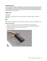
1. Remove the hinge cover. See “Hinge cover” on page 57.
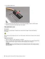
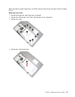
2. Remove the computer back cover. See “Computer back cover” on page 58.
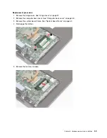
3. Remove the system board frame. See “System board frame” on page 62.
4. Remove the system fan. See “System fan” on page 66.
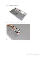
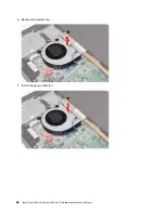
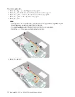
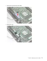
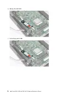
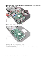
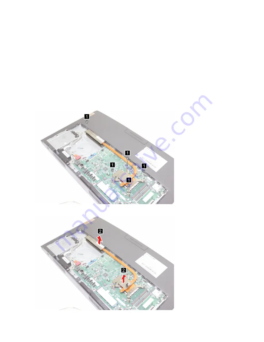
5. Remove the screws.
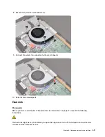
Notes:
• Carefully remove the screws from the system board to avoid any possible damage to the system
board. The screws cannot be removed from the heat sink.
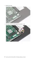
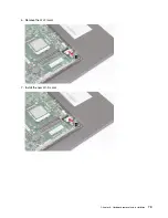
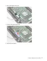
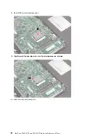
• You might have to gently twist the heat sink to free it from the microprocessor.
• Do not touch the thermal grease while handling the heat sink.
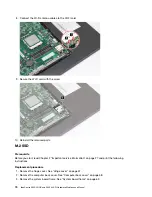
6. Remove the heat sink.
70
IdeaCentre A540-24ICB and A540-24API Hardware Maintenance Manual
Summary of Contents for IdeaCentre A540-24API
Page 1: ...IdeaCentre A540 24ICB and A540 24API Hardware Maintenance Manual ...
Page 6: ...iv IdeaCentre A540 24ICB and A540 24API Hardware Maintenance Manual ...
Page 13: ...Chapter 1 Important safety information 7 ...
Page 17: ...Chapter 1 Important safety information 11 ...
Page 18: ...1 2 12 IdeaCentre A540 24ICB and A540 24API Hardware Maintenance Manual ...
Page 19: ...Chapter 1 Important safety information 13 ...
Page 25: ...Chapter 1 Important safety information 19 ...
Page 29: ...Chapter 1 Important safety information 23 ...
Page 38: ...32 IdeaCentre A540 24ICB and A540 24API Hardware Maintenance Manual ...
Page 46: ...40 IdeaCentre A540 24ICB and A540 24API Hardware Maintenance Manual ...
Page 65: ...3 Remove the screws 4 Unplug the connectors Chapter 6 Hardware removal and installation 59 ...
Page 111: ...3 Remove the rubber feet 4 Remove the screws Chapter 6 Hardware removal and installation 105 ...
Page 129: ......
Page 130: ......


