


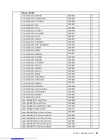


Liteon SK-8861(BE-EN) 2.4G KB Only-S8
25210197
2
Liteon SK-8861(US-EU) 2.4G KB Only-S8
25210198
2
Liteon SK-8861(RU) 2.4G KB-Silver8
25210199
2
Liteon SK-8861(CS-SK) 2.4G KB-Silver8
25210200
2
Liteon SK-8861(JP) 2.4G KB Only-Silver8
25210201
2
Liteon SK-8861(Nordic) 2.4G KB Only-S8
25210652
2
Liteon SK-8861(IT) 2.4G KB Only-Silver8
25210653
2
Liteon SK-8861(CH) 2.4G KB Only-Silver8
25210752
2
Liteon SK-8861(ES) 2.4G KB Only-Silver8
25210654
2
Liteon SK-8861(TW) 2.4G KB Only-Silver8
25210190
2
Liteon SK-8861(KR) 2.4G KB Only-Silver8
25210191
2
Liteon SK-8861(LA-AR) 2.4G KB Only-S8
25210192
2
Liteon SK-8861(LA) 2.4G KB Only-Silver8
25210194
2
Liteon SK-8861(US-IN) 2.4G KB Only-S8
25210196
2
Liteon SK-8861(SA) 2.4G KB Only-Silver8
25210744
2
Liteon N70 2.4G mouse+D for Silver Silk
25209297
2
Liteon N70 2.4G mouse+D for S Silk JP
25210202
2
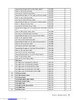
Power Cord
longwell Black Single-end 1.0m3wire ULCSA Power Cable
31033857
1
Volex 1m C5 US Power Cable
31033858
1
Luxshare1.0m C5 US Power Cable
31049517
1
longwell Black Single-end 1.0m SAA Power Cable
31035397
1
Volex 1m C5 Australia Power Cable
31049500
1
Luxshare1.0m C5 Australia Power Cable
31049520
1
Longwell 1.0M C5 2pin Japan power cord
31503423
1
Volex1.0M C5 2pin Japan power cord
31503424
1
Luxshare 1.0M C5 2pin Japan power cord
31503425
1
Grandsun Black Single-end 1.0m3wire CCC Power Cable (R)
31032953
1
Luxshare1.0M C5 CCC Power Cable
31045147
1
longwell Black Single-end 1.0m ASTA Power Cable
31035396
1
Volex 1m C5 UK Power Cable
31049496
1
Luxshare1.0m C5 UK Power Cable
31503352
1
longwell Black Single-end 1.0m VDE Power Cable
31035332
1
Volex 1m C5 Europe Power Cable
31049497
1
Luxshare1.0m C5 Europe Power Cable
31049518
1
longwell Black Single-end 1.0m India Power Cable
31035395
1
Luxshare1.0m C5 India Power Cable
31503353
1
Longwell Black Single-end 1.0m Italy C5 Power Cable ®
31039104
1
Volex 1m C5 Italy Power Cable
31049504
1
Luxshare1.0m C5 Italy Power Cable
31503359
1
66
IdeaCentre A730Hardware Maintenance Manual
Summary of Contents for IdeaCentre A730
Page 2: ......
Page 3: ...IdeaCentre A730 Hardware Maintenance Manual Machine Types 10123 F0A0 A730 ...
Page 6: ...iv IdeaCentre A730Hardware Maintenance Manual ...
Page 8: ...2 IdeaCentre A730Hardware Maintenance Manual ...
Page 16: ...10 IdeaCentre A730Hardware Maintenance Manual ...
Page 18: ...12 IdeaCentre A730Hardware Maintenance Manual ...
Page 24: ...18 IdeaCentre A730Hardware Maintenance Manual ...
Page 34: ...28 IdeaCentre A730Hardware Maintenance Manual ...


