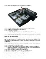
Step 7.
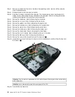
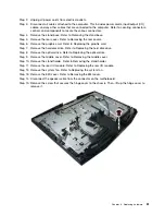
Remove the hard disk drive. Refer to Replacing the hard disk drive.
Step 8.
Remove the optical drive. Refer to Replacing the optical drive.
Step 9.
Remove the middle cover. Refer to Removing the middle cover.
Step 10. Remove the stand holder. Refer to Removing the stand holder.
Step 11. Remove the rear I/O module. Refer to Replacing the rear I/O module.
Step 12. Remove the EMI cover. Refer to Removing the EMI cover.
Step 13. Remove the mother board. Refer to Replacing the motherboard.
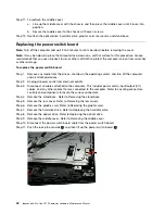
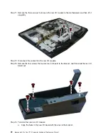
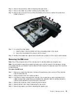
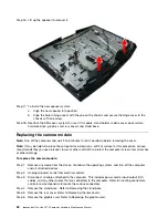
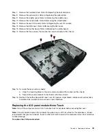
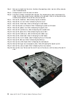
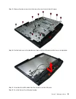
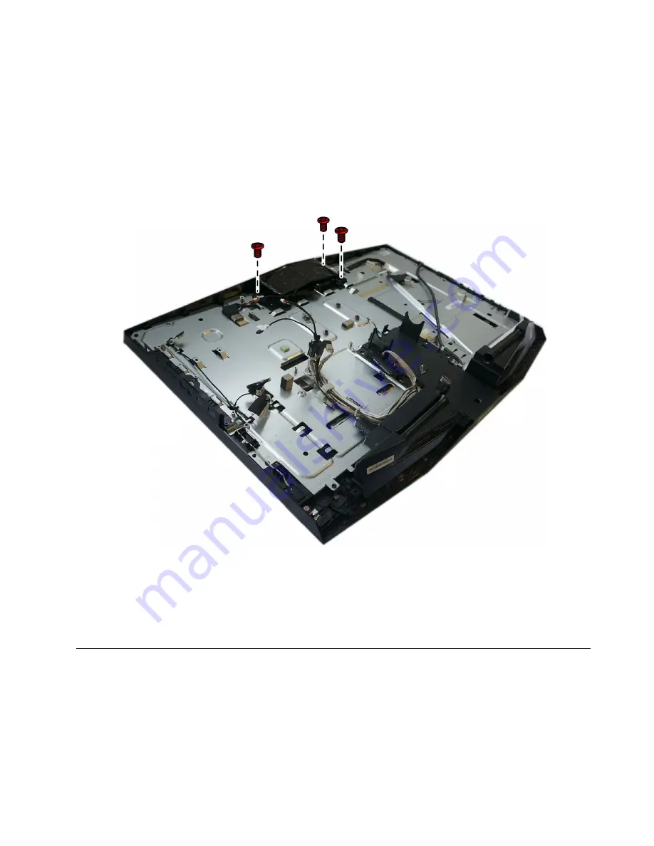
Step 14. Remove the three screws that secure the camera module to the chassis.
Step 15. To install the new camera module:
a.
Align the mounting holes on the new camera module with the ones on the chassis.
b.
Secure the camera module to the chassis with three screws.
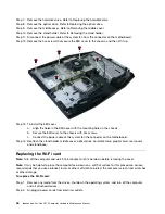
Step 16. Reattach the mother board, EMI cover, rear I/O module, stand holder, middle cover, optical drive,
hard disk drive, graphic card, rear covers and stand base.
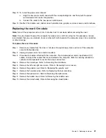
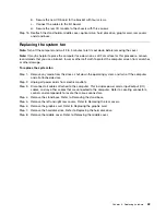
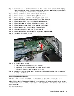
Replacing the LCD panel module-None Touch
Note:
Turn off the computer and wait 3 to 5 minutes to let it cool down before removing the cover.
Note:
It may be helpful to place the computer face-down on a soft flat surface for this procedure. Lenovo
recommends that you use a blanket, towel, or other soft cloth to protect the computer screen from scratches
or other damage.
To replace the LCD panel module:
.
53
Summary of Contents for ideacentre All-In-One Y910
Page 2: ......
Page 6: ...iv ideacentre All In One Y910 Computer Hardware Maintenance Manual ...
Page 8: ...2 ideacentre All In One Y910 Computer Hardware Maintenance Manual ...
Page 16: ...10 ideacentre All In One Y910 Computer Hardware Maintenance Manual ...
Page 18: ...12 ideacentre All In One Y910 Computer Hardware Maintenance Manual ...
Page 24: ...18 ideacentre All In One Y910 Computer Hardware Maintenance Manual ...
Page 68: ...62 ideacentre All In One Y910 Computer Hardware Maintenance Manual ...


