background image

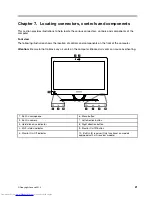
Chapter 8. Replacing hardware

Attention:

Do not remove the computer cover or attempt any repair before reading the “Important safety information”

in the Safety and Warranty Guide that was included with your computer. To obtain copies of the Safety and Warranty
Guide, go to the Support Web site at: http://consumersupport.lenovo.com.

Note:

Use only parts provided by Lenovo.
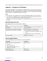
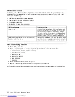
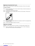
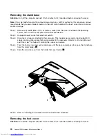
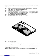
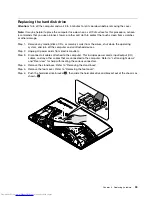
General information

Pre-disassembly instructions

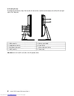
Before starting the disassembly procedure, make sure that you do the following:

1. Turn off the power to the system and all peripherals.

2. Unplug all power and signal cables from the computer.

3. Place the system on a flat, stable surface.

© Copyright Lenovo 2012

27

Summary of Contents for IdeaCentre C540

Page 1: ...Lenovo C540 Hardware Maintenance Manual ideaideaideaCentreidea Machine Types 10110 6267 C540 ...

Page 2: ......

Page 3: ...Lenovo C540 Hardware Maintenance Manual Machine Types 10110 6267 C540 ...

Page 4: ...ight Lenovo 2012 LIMITED AND RESTRICTED RIGHTS NOTICE If data or software are delivered pursuant a General Services Administration GSA contract use reproduction or disclosure is subject to restrictions set forth in Contract No GS 35F 05925 ...

Page 5: ...oblems 20 Chapter 7 Locating connectors controls and components 21 Chapter 8 Replacing hardware 27 General information 27 Replacing the keyboard and mouse 28 Replacing the adapter 28 Removing the stand base 30 Removing the foot cover 30 Replacing a memory module 31 Replacing the hard disk drive 33 Replacing the optical drive 34 Removing the stand holder 36 Removing the middle cover 37 Replacing th...

Page 6: ...iv Lenovo C540Hardware Maintenance Manual ...

Page 7: ...ON and DANGER sections in this manual before following any of the instructions Veuillez lire toutes les consignes de type DANGER et ATTENTION du présent document avant d exécuter les instructions Lesen Sie unbedingt alle Hinweise vom Typ ACHTUNG oder VORSICHT in dieser Dokumentation bevor Sie irgendwelche Vorgänge durchführen Leggere le istruzioni introdotte da ATTENZIONE e PERICOLO presenti nel m...

Page 8: ...2 Lenovo C540Hardware Maintenance Manual ...

Page 9: ...from areas that people may walk through to ensure no one trips over it Do not wear loose clothing that can be trapped in the moving parts of a machine Ensure that your sleeves are fastened or rolled up above your elbows If your hair is long tie or fasten it back Insert the ends of your necktie or scarf inside clothing or fasten it with a non conductive clip approximately 8 centimeters 3 inches fro...

Page 10: ...There must be a complete circuit to cause electrical shock By observing the above rule you may prevent a current from passing through your body When using a tester set the controls correctly and use the approved probe leads and accessories for that tester Stand on suitable rubber mats obtained locally if necessary to insulate you from grounds such as metal floor strips and machine frames Observe t...

Page 11: ...connect the power cord 3 Check the power cord for a A third wire ground connector in good condition Use a meter to measure third wire ground continuity for 0 1 ohm or less between the external ground pin and frame ground b The power cord should be the appropriate type as specified in the parts listings c Insulation must not be frayed or worn 4 Remove the cover 5 Check for any obvious alterations U...

Page 12: ...s Electrical grounding of the computer is required for operator safety and correct system function Proper grounding of the electrical outlet can be verified by a certified electrician Safety notices The CAUTION and DANGER safety notices in this section are provided in the language of English DANGER Electrical current from power telephone and communication cables is hazardous To avoid a shock hazar...

Page 13: ...row into or immerse in water Heat to more than 100 C 212 F Repair or disassemble Dispose of the battery as required by local ordinances or regulations CAUTION When laser products such as CD ROMs DVD ROM drives fiber optic devices or transmitters are installed note the following Do not remove the covers Removing the covers of the laser product could result in exposure to hazardous laser radiation T...

Page 14: ...y do not turn off the electrical current supplied to the device The device also might have more than one power cord To remove all electrical current from the device ensure that all power cords are disconnected from the power source 1 2 CAUTION Do not place any object weighing more than 82 kg 180 lbs on top of rack mounted devices 8 Lenovo C540Hardware Maintenance Manual ...

Page 15: ...tions for your computer This section lists the physical specifications for your computer Type Lenovo C540 This section lists the physical specifications Environment Air temperature Operating 10 to 35 C Transit 20 to 55 C Humidity Operating 35 to 80 Transit 20 to 90 40 C Altitude 86KPa to 106KPa Electrical input Input voltage 90V 264V AC Input frequency 47Hz 63Hz Copyright Lenovo 2012 9 ...

Page 16: ...10 Lenovo C540Hardware Maintenance Manual ...

Page 17: ...cedure to help determine the cause of the problem 1 Power off the computer and all external devices 2 Check all cables and power cords 3 Set all display controls to the middle position 4 Power on all external devices 5 Power on the computer Look for displayed error codes Look for readable instructions or a main menu on the display If you did not receive the correct response proceed to step 6 If yo...

Page 18: ...12 Lenovo C540Hardware Maintenance Manual ...

Page 19: ...ee Starting the Setup Utility program You must use the keyboard when using the Lenovo BIOS Setup Utility menu The keys used to perform various tasks are displayed on the bottom of each screen Using passwords You can use the Lenovo BIOS Setup Utility program to set passwords to prevent unauthorized persons from gaining access to your computer and data See Starting the Setup Utility program The foll...

Page 20: ...word do the following 1 Start the Lenovo BIOS Setup Utility program see Starting the Lenovo BIOS Setup Utility program on page 13 2 From the Security menu select Set Administrator Password and press the Enter key 3 The password dialog box will be displayed Type the current password then press the Enter key 4 Type the new password then press the Enter key Re type the password to confirm the new pas...

Page 21: ...n Password leave each new password line item blank then press Enter A Setup Notice confirming that changes have been saved will be displayed 4 Return to the Lenovo BIOS Setup Utility program menu and select the Exit option 5 Select Save changes and Exit from the menu Enabling or disabling a device The Devices options is used to enable or disable user access to the following devices USB Functions S...

Page 22: ... the computer When the Startup Device Menu appears release the F12 key Note If the Startup Device Menu does not display using these steps repeatedly press and release the F12 key rather than keeping it pressed when turning on the computer 3 Use and arrows to select the desired startup device from the Startup Device Menu and press the Enter key to begin Note Selecting a startup device from the Star...

Page 23: ... program main menu You might have to press the Esc key several times Do one of the following If you want to save the new settings select Save changes and Exit from the menu When the Save reset window shows select the Yes button and then press the Enter key to exit the Lenovo BIOS Setup Utility program If you do not want to save the settings select Discard changes and Exit from the menu When the Re...

Page 24: ...18 Lenovo C540Hardware Maintenance Manual ...

Page 25: ...d disk drive boot error A hard disk drive boot error can be caused by the following Error FRU Action The startup drive is not included in the boot sequence configuration Check the configuration and ensure the startup drive is in the boot sequence No operating system is installed on the boot drive Install an operating system on the boot drive The boot sector on the startup drive is corrupted The dr...

Page 26: ...in Startup and set the option to Enabled The BIOS then ignores the missing keyboard during POST Reboot and Select proper Boot device or Insert Boot Media in selected Boot device The BIOS was unable to find a suitable boot device Make sure the boot drive is properly connected to the computer Make sure you have bootable media in the boot device Undetermined problems 1 Power off the computer 2 Remove...

Page 27: ...ont of the computer Attention Be careful not to block any air vents on the computer Blocked air vents can cause overheating 1 2 3 7 6 5 4 8 9 10 1 Built in microphone 6 Menu button 2 Built in camera 7 Left direction button 3 Hard disk drive indicator 8 Right direction button 4 Wi Fi status indicator 9 Monitor On Off button 5 Monitor On Off indicator 10 Built in IR receiver Only functional on model...

Page 28: ... left and right side of the computer 1 2 3 6 5 4 7 8 1 USB connector 5 Memory card reader 2 Headphone connector 6 Power button 3 Microphone connector 7 Optical drive eject button 4 USB connector 8 Optical drive Attention Do not insert 3 inch discs into the optical drive 22 Lenovo C540Hardware Maintenance Manual ...

Page 29: ...1 TV tuner connector selected models only 2 connectors for Japan 6 USB connector 2 TV tuner connector selected models only 2 connectors for Japan 7 HDMI out connector selected models only 3 Power connector 8 Security cable slot 4 Ethernet connector 9 Air vents 5 USB connector Chapter 7 Locating connectors controls and components 23 ...

Page 30: ...d 12 Wi Fi card 2 Foot cover 13 TV Tuner card 3 Middle cover 14 System fan 4 EMI cover 15 Heat sink 5 Motherboard 16 Camera 6 Power switch board 17 Hard disk drive and bay 7 Speakers 18 Converter board 8 Rear I O module 19 Front function board 9 Chassis 20 Optical drive 10 LED panel 21 Optical drive bracket 11 Front bezel 24 Lenovo C540Hardware Maintenance Manual ...

Page 31: ...Thermal sensor header 13 TV Tuner card connector 2 CPU and socket 14 Rear I O module connector 3 Memory connector 15 DC in connector 4 USB connectors 16 B Case card connector 5 Headphone connector 17 Converter board connector 6 Microphone connector 18 Hard disk drive SATA connector 7 Memory card connector 19 Hard disk drive power connector 8 Speaker connector 20 Optical drive SATA connector 9 Powe...

Page 32: ...26 Lenovo C540Hardware Maintenance Manual ...

Page 33: ...he Safety and Warranty Guide go to the Support Web site at http consumersupport lenovo com Note Use only parts provided by Lenovo General information Pre disassembly instructions Before starting the disassembly procedure make sure that you do the following 1 Turn off the power to the system and all peripherals 2 Unplug all power and signal cables from the computer 3 Place the system on a flat stab...

Page 34: ... the keyboard Refer to Side view of the computer and Rear view of the computer Step 4 Disconnect the defective keyboard cable from the computer and connect the new keyboard cable to the same connector Step 5 The mouse can be replaced using the same method Replacing the adapter Attention Turn off the computer and wait 3 to 5 minutes to let it cool down before removing the cover Step 1 Remove any me...

Page 35: ...Step 2 Disconnect the adapter cable from the computer 1 then unplug the power cord from electrical outlet 2 Step 3 Connect the new adapter as shown 1 2 Chapter 8 Replacing hardware 29 ...

Page 36: ...er cords from electrical outlets Step 3 Disconnect all cables attached to the computer This includes power cords input output I O cables and any other cables that are connected to the computer Refer to Left and right views and Rear view for help with locating the various connectors Step 4 Twist the hand screw ring counter clockwise until the base comes loose to release the stand base from the stan...

Page 37: ... the computer This includes power cords input output I O cables and any other cables that are connected to the computer Refer to Left and right views and Rear view for help with locating the various connectors Step 4 Remove the foot base Refer to Removing the foot base Step 5 Lift up the stand holder then slide out the foot cover as shown Step 6 To reattach the foot cover a Lift up the stand holde...

Page 38: ...hat are connected to the computer Refer to Left and right views and Rear view for help with locating the various connectors Step 4 Remove the stand base Refer to Removing the stand base Step 5 Remove the foot cover Refer to Removing the foot cover Step 6 Push out the latches on both sides of the memory socket to release the memory module 1 and gently pull the memory module upward to remove it from...

Page 39: ...ting system and turn off the computer and all attached devices Step 2 Unplug all power cords from electrical outlets Step 3 Disconnect all cables attached to the computer This includes power cords input output I O cables and any other cables that are connected to the computer Refer to Left and right views and Rear view for help with locating the various connectors Step 4 Remove the stand base Refe...

Page 40: ...ovo recommends that you use a blanket towel or other soft cloth to protect the touch screen from scratches or other damage Step 1 Remove any media disks CDs or memory cards from the drives shut down the operating system and turn off the computer and all attached devices Step 2 Unplug all power cords from electrical outlets Step 3 Disconnect all cables attached to the computer This includes power c...

Page 41: ... paper clip into the small hole on the optical drive cover so that the disk springs out as shown Step 8 Remove the 2 screws that secure the optical drive to the metal bracket 1 Step 9 Use a small flat head screwdriver to press and push out the pins that secure the cover to the disk 2 3 Chapter 8 Replacing hardware 35 ...

Page 42: ...h to protect the computer screen from scratches or other damage To remove the stand holder Step 1 Remove any media disks CDs DVDs or memory cards from the drives shut down the operating system and turn off the computer and all attached devices Step 2 Unplug all power cords from electrical outlets Step 3 Disconnect all cables attached to the computer This includes power cords input output I O cable...

Page 43: ...e cover Step 1 Remove any media disks CDs DVDs or memory cards from the drives shut down the operating system and turn off the computer and all attached devices Step 2 Unplug all power cords from electrical outlets Step 3 Disconnect all cables attached to the computer This includes power cords input output I O cables and any other cables that are connected to the computer Refer to Left and right v...

Page 44: ...oard Step 1 Remove any media disks CDs DVDs or memory cards from the drives shut down the operating system and turn off the computer and all attached devices Step 2 Unplug all power cords from electrical outlets Step 3 Disconnect all cables attached to the computer This includes power cords input output I O cables and any other cables that are connected to the computer Refer to Left and right view...

Page 45: ...use a blanket towel or other soft cloth to protect the computer screen from scratches or other damage To replace the EMI cover Step 1 Remove any media disks CDs DVDs or memory cards from the drives shut down the operating system and turn off the computer and all attached devices Step 2 Unplug all power cords from electrical outlets Step 3 Disconnect all cables attached to the computer This include...

Page 46: ...Reattach the middle cover optical drive stand holder foot cover and stand base Replacing the rear I O module Note Turn off the computer and wait 3 to 5 minutes to let it cool down before removing the cover Note It may be helpful to place the computer face down on a soft flat surface for this procedure Lenovo recommends that you use a blanket towel or other soft cloth to protect the computer screen...

Page 47: ...TV antenna cable s from the TV tuner card Step 12 Remove the hexagonal nut that secure the TV Tuner antenna connector to the rear I O bracket Then slide the TV Tuner antenna connector out Step 13 Remove the one screw that secures the power jack to the bracket Slide out the power jack from the rear I O bracket Step 14 To install the new rear I O module a Attach the TV Tuner antenna connector and po...

Page 48: ... the EMI cover Refer to Removing the EMI cover Step 10 Disconnect the antenna cable from the TV Tuner card Step 11 Remove the screw that secures the TV Tuner card to the motherboard Step 12 Pull the TV Tuner card upward to remove it from the card port on the motherboard Step 13 To install the new TV Tuner card a Insert the notched end of the TV Tuner card into the card port on the motherboard b Se...

Page 49: ...e WLAN card Step 11 Remove the screw that secures the WLAN card to the motherboard Step 12 Lift up the WLAN card to remove it from the socket Step 13 To install the new WLAN card a Insert the notched end of the WLAN card into the card port on the motherboard b Secure new the WLAN card to the motherboard with the screw c Connect the antenna cables to the new WLAN card Step 14 Reattach the EMI cover...

Page 50: ...ion then secure it with the rubber screws b Connect the new speaker cables to the connector on the motherboard Step 13 Reattach the EMI cover middle cover optical drive stand holder foot cover and stand base Replacing the system fan Note Turn off the computer and wait 3 to 5 minutes to let it cool down before removing the cover Note It may be helpful to place the computer face down on a soft flat ...

Page 51: ...fan and heat sink Step 15 Reattach the EMI cover middle cover optical drive stand holder foot cover and stand base Replacing the heat sink Note Turn off the computer and wait 3 to 5 minutes to let it cool down before removing the cover Note It may be helpful to place the computer face down on a soft flat surface for this procedure Lenovo recommends that you use a blanket towel or other soft cloth ...

Page 52: ...e new heat sink with mounting holes on the motherboard then place it into position b Follow the numbers printed on the new heat sink to secure it in order using the eight screws c Use the sealing tape to seal the gap in between the system fan and heat sink Step 14 Reattach the EMI cover middle cover optical drive stand holder foot cover and stand base Replacing the camera Note Turn off the compute...

Page 53: ...front bezel Step 12 Lift up the camera and disconnect the data cable from the camera 1 2 Step 13 Remove the two screws that secure the camera to the bracket then put aside the bracket Step 14 To install the new camera a Line up the new camera with the bracket then secure the camera to the bracket with the two screws b Connect the data cable to the new camera c Line up the holes in the new camera w...

Page 54: ...r to Removing the foot cover Step 6 Remove the optical drive Refer to Replacing the optical drive Step 7 Remove the stand holder Refer to Removing the stand holder Step 8 Remove the middle cover Refer to Removing the middle cover Step 9 Remove the EMI cover Refer to Removing the EMI cover Step 10 Remove the heat sink Refer to Replacing the heat sink Step 11 Lift the small handle and open the retai...

Page 55: ...ts keep the microprocessor completely level while installing it into the socket Step 15 Lower the microprocessor straight down into its socket on the motherboard Step 16 To secure the microprocessor in the socket close the microprocessor retainer and lock it into position with the small handle Step 17 Use a thermal grease syringe to place 5 drops of grease on the top of the microprocessor Each dro...

Page 56: ... view and Rear view for help with locating the various connectors Step 4 Remove the stand base Refer to Removing the stand base Step 5 Remove the foot cover Refer to Removing the foot cover Step 6 Remove the optical drive Refer to Replacing the optical drive Step 7 Remove the stand holder Refer to Removing the stand holder Step 8 Remove the middle cover Refer to Removing the middle cover Step 9 Re...

Page 57: ...wer cords input output I O cables and any other cables that are connected to the computer Refer to Left and right view and Rear view for help with locating the various connectors Step 4 Remove the stand base Refer to Removing the stand base Step 5 Remove the foot cover Refer to Removing the foot cover Step 6 Remove the optical drive Refer to Replacing the optical drive Step 7 Remove the stand hold...

Page 58: ...the various connectors Step 4 Remove the stand base Refer to Removing the stand base Step 5 Remove the foot cover Refer to Removing the foot cover Step 6 Remove the memory modules Refer to Replacing a memory module Step 7 Remove the optical drive Refer to Replacing the optical drive Step 8 Remove the stand holder Refer to Removing the stand holder Step 9 Remove the middle cover Refer to Removing t...

Page 59: ...l Note Turn off the computer and wait 3 to 5 minutes to let it cool down before removing the cover Note It may be helpful to place the computer face down on a soft flat surface for this procedure Lenovo recommends that you use a blanket towel or other soft cloth to protect the computer screen from scratches or other damage To replace the LED panel Step 1 Remove any media disks CDs DVDs or memory c...

Page 60: ...rd Step 14 Remove the nine screws that secure the chassis to the front bezel Step 15 Remove the two screws that secure the LED panel to the chassis Step 16 Disconnect the converter cable and LVDS cable from the connectors on the LED panel Step 17 Lift up the chassis to separate the LED panel from the chassis Step 18 To install the new the LED panel a Line up the chassis with new LED panel and then...

Page 61: ...Step 19 Reattach the system fan speaker system EMI cover middle cover stand holder optical drive foot cover and stand base Chapter 8 Replacing hardware 55 ...

Page 62: ...56 Lenovo C540Hardware Maintenance Manual ...

Page 63: ...a 1 or 2 in the CRU column are Customer Replaceable Units CRUs 1 identifies parts that are fairly simple to replace requiring few or no tools 2 identifies parts that are slightly more difficult to replace N identifies parts that are not to be replaced by the customer 1 2 3 6 7 8 9 10 11 14 18 16 17 15 19 20 21 4 5 12 13 Item Description Service Part Number CRU ID 1 Computer stand Copyright Lenovo ...

Page 64: ...ACK COVER W TV W O HDMI_ODD BK 90202206 N C540 BACK COVER W TV W O HDMI_ODD WH 90202207 N C540 BACK COVER W HDMI W O TV_ODD BK 90202208 N C540 BACK COVER W HDMI W O TV_ODD WH 90202209 N C540 BACK COVER W O TV_HDMI W ODD BK 90202210 N C540 BACK COVER W O TV_HDMI W ODD WH 90202211 N 4 EMI cover C540 EMI SHIELDING 90202096 N 5 Motherboard C540 NON_WIN8 UMA W USB3 0 MB 90001459 N C540 NON_WIN8 UMA W O...

Page 65: ...512M_GPU W O USB3 0 MB 90001478 N C540 WIN8 1G_GPU W USB3 0 MB 90001479 N C540 WIN8 1G_GPU W O USB3 0 MB 90001480 N C540 WIN8 2G_GPU W USB3 0 MB 90001481 N C540 WIN8 2G_GPU W O USB3 0 MB 90001482 N 6 Power switch board N C540 LED POWER BOARD W SWTV 90001760 N C540 LED POWER BOARD W O SWTV 90001761 N 7 Speakers N C540 Speaker L R 90201931 N 8 Rear I O module 9 Chassis N C540 MAIN FRAME FOR SAM 9020...

Page 66: ... System fan N C540 AVC Fan 90201929 N C540 Delta Fan 90201930 N 15 Heat sink N C540 AVC UMA HeatSink 90201925 N C540 Coolermaster UMA HeatSink 90201926 N C540 AVC DIS HeatSink 90201927 N C540 Coolermaster DIS HeatSink 90201928 N 16 Camera Bison M720P VC OV9712 CAM 20200085 N CCY M720P VC OV9712 CAM 20200086 N 17 Hard disk drive and bay SGT Pharaoh 4K ST500DM002 500G HDD LH 16200178 1 SGT Grenada S...

Page 67: ... BOARD FOR LG 90001758 N C540 CONVERT BOARD FOR CMI 90001759 N 19 Front function board C540 FUNCTION BOARD 90001762 N 20 Optical drive HLDS GT50N 25201635 N PLDS DS 8A9SH 25209016 N HLDS GT80N 25209015 N 21 Optical drive bracket Chapter 9 FRU lists 61 ...

Page 68: ...62 Lenovo C540Hardware Maintenance Manual ...

Page 69: ...S As this computer has an ACPI BIOS system the operating system is allowed to control the power management features of the computer and the settings for Advanced Power Management APM BIOS mode is ignored Not all operating systems support ACPI BIOS mode Automatic Power On features The Automatic Power On features within the Power Management menu allow you to enable and disable features that turn on ...

Reviews: