background image

Lenovo H520e Hardware Maintenance Manual

i

d

e

a

i

d

e

a

i

d

e

a

C

entrei

d

e

a

Machine Types:

90AM

Summary of Contents for ideaCentre H520e

Page 1: ...Lenovo H520e Hardware Maintenance Manual ideaideaideaCentreidea Machine Types 90AM ...

Page 2: ...tion on page 3 and Appendix A Notices on page 101 First Edition January 2013 Copyright Lenovo 2013 LIMITED AND RESTRICTED RIGHTS NOTICE If data or software is delivered pursuant a General Services Administration GSA contract use reproduction or disclosure is subject to restrictions set forth in Contract No GS 35F 05925 ...

Page 3: ...nsiderations 54 Power On Password 54 Administrator Password 54 Hard Disk Password 54 Setting changing and deleting a password 54 Erasing lost or forgotten passwords clearing CMOS 55 Enabling or disabling a device 55 Selecting a startup device 55 Selecting a temporary startup device 55 Selecting or changing the startup device sequence 56 Enabling ErP compliance mode 56 Changing the BIOS settings be...

Page 4: ...7 Operating system password 97 Vital Product Data 97 BIOS levels 97 Flash update procedures 97 Updating flashing the BIOS from a disc 98 Updating flashing the BIOS from your operating system 99 Recovering from a POST and BIOS update failure 99 Power management 100 Advanced Configuration and Power Interface ACPI BIOS 100 Automatic Power on features 100 Appendix A Notices 101 Television output notic...

Page 5: ...U replacement instructions see Chapter 9 Replacing FRUs on page 69 Important safety information Be sure to read all caution and danger statements in this manual before performing any of the instructions Veuillez lire toutes les consignes de type DANGER et ATTENTION du présent document avant d exécuter les instructions Lesen Sie unbedingt alle Hinweise vom Typ ACHTUNG oder VORSICHT in dieser Dokume...

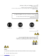
Page 6: ...2 Lenovo H520e Hardware Maintenance Manual ...

Page 7: ...that other people will not trip over it Do not wear loose clothing that can be trapped in the moving parts of a machine Ensure that your sleeves are fastened or rolled up above your elbows If your hair is long fasten it Insert the ends of your necktie or scarf inside clothing or fasten it with a nonconductive clip approximately 8 centimeters 3 inches from the end Do not wear jewelry chains metal f...

Page 8: ...e must be a complete circuit to cause an electric shock By observing the above rule you may prevent a current from passing through your body When using a tester set the controls correctly and use the approved probe leads and accessories for that tester Stand on suitable rubber mats obtained locally if necessary to insulate you from grounds such as metal floor strips and machine frames Observe the ...

Page 9: ...inspection guide The intent of this inspection guide is to assist you in identifying potentially unsafe conditions on these products Each machine as it was designed and built had required safety items installed to protect users and service personnel from injury This guide addresses only those items However good judgment should be used to identify potential safety hazards due to attachment of featu...

Page 10: ...rt Wear a grounded wrist strap against your skin to eliminate static on your body Prevent the part from touching your clothing Most clothing is insulative and retains a charge even when you are wearing a wrist strap Use the black side of a grounded work mat to provide a static free work surface The mat is especially useful when handling ESD sensitive devices Select a grounding system such as those...

Page 11: ...he installation and configuration procedures Connect and disconnect cables as described in the following tables when installing moving or opening covers on this product or attached devices To Connect To Disconnect 1 Turn everything OFF 2 First attach all cables to devices 3 Attach signal cables to connectors 4 Attach power cords to outlet 5 Turn device ON 1 Turn everything OFF 2 First remove power...

Page 12: ...on exposure DANGER Some laser products contain an embedded Class 3A or Class 3B laser diode Note the following Laser radiation when open Do not stare into the beam do not view directly with optical instruments and avoid direct exposure to the beam 18 kg 37 lbs 32 kg 70 5 lbs 55 kg 121 2 lbs CAUTION Use safe practices when lifting CAUTION The power control button on the device and the power switch ...

Page 13: ...Chapter 2 Safety information 9 ...

Page 14: ... 18 kg 37 lbs 32 kg 70 5 lbs 55 kg 121 2 lbs 1 2 PERIGO A corrente elétrica proveniente de cabos de alimentação de telefone e de comunicações é perigosa 10 Lenovo H520e Hardware Maintenance Manual ...

Page 15: ...s aos dispositivos 3 Conecte os cabos de sinal aos conectores 4 Conecte os cabos de alimentação às tomadas 5 LIGUE os dispositivos 1 DESLIGUE Tudo 2 Primeiramente remova os cabos de alimentação das tomadas 3 Remova os cabos de sinal dos conectores 4 Remova todos os cabos dos dispositivos CUIDADO Ao substituir a bateria de lítio utilize apenas uma bateria com Número de Peça 45C1566 ou um tipo de ba...

Page 16: ...e evite exposição direta ao feixe 18 kg 37 lbs 32 kg 70 5 lbs 55 kg 121 2 lbs CUIDADO Utilize procedimentos de segurança para levantar equipamentos CUIDADO O botão de controle de alimentação do dispositivo e o botão para ligar desligar da fonte de alimentação não desligam a corrente elétrica fornecida ao dispositivo O dispositivo também pode ter mais de um cabo de alimentação Para remover toda a c...

Page 17: ...Chapter 2 Safety information 13 ...

Page 18: ...1 2 14 Lenovo H520e Hardware Maintenance Manual ...

Page 19: ...1 2 Chapter 2 Safety information 15 ...

Page 20: ...ésent produit ou des périphériques qui lui sont raccordés reportez vous aux instructions ci dessous pour connecter et déconnecter les différents cordons Connexion Déconnexion 1 Mettez les unités HORS TENSION 2 Commencez par brancher tous les cordons sur les unités 3 Branchez les câbles d interface sur des connecteurs 4 Branchez les cordons d alimentation sur des prises 5 Mettez les unités SOUS TEN...

Page 21: ...à laser contiennent une diode à laser intégrée de classe 3A ou 3B Prenez connaissance des informations suivantes Rayonnement laser lorsque le carter est ouvert Evitez toute expositiondirecte au rayon laser Evitez de regarder fixement le faisceau ou del observer à l aide d instruments optiques 18 kg 37 lbs 32 kg 70 5 lbs 55 kg 121 2 lbs ATTENTION Soulevez la machine avec précaution ATTENTION L inte...

Page 22: ...alten sind Zum Installieren Transportieren und Öffnen der Abdeckungen des Computers oder der angeschlossenen Einheiten die Kabel gemäß der folgenden Tabelle anschließen und abziehen Zum Anschließen der Kabel gehen Sie wie folgt vor Zum Abziehen der Kabel gehen Sie wie folgt vor 1 Schalten Sie alle Einheiten AUS 2 Schließen Sie erst alle Kabel an die Einheiten an 3 Schließen Sie die Signalkabel an ...

Page 23: ...hier angegeben verwendet kann gefährliche Laserstrahlung auftreten VORSICHT Einige Lasergeräte enthalten eine Laserdiode der Klasse 3A oder 3B Beachten Sie Folgendes Laserstrahlung bei geöffneter Verkleidung Nicht in den Strahl blicken Keine Lupen oder Spiegel verwenden Strahlungsbereich meiden 18 kg 32 kg 55 kg ACHTUNG Arbeitsschutzrichtlinien beim Anheben der Maschine beachten ACHTUNG Mit dem Ne...

Page 24: ...1 2 20 Lenovo H520e Hardware Maintenance Manual ...

Page 25: ...1 2 Chapter 2 Safety information 21 ...

Page 26: ...zioni di installazione spostamento o apertura dei coperchi di questo prodotto o delle unità collegate Per collegarsi Per scollegarsi 1 SPEGNERE le apparecchiature 2 Innanzitutto collegare tutti i cavi alle unità 3 Collegare i cavi di segnale ai connettori 4 Collegare i cavi di alimentazione alla presa 5 Accendere l unità 1 SPEGNERE le apparecchiature 2 Innanzitutto rimuovere i cavi di alimentazion...

Page 27: ...laser contengono un diodo laser di Classe 3A o Classe 3B Tener presente quanto segue Aprendo l unità vengono emesse radiazioni laser Non fissare il fascio non guardarlo direttamente con strumenti ottici ed evitare l esposizione al fascio 18 kg 32 kg 55 kg ATTENZIONE Prestare attenzione nel sollevare l apparecchiatura ATTENZIONE Il pulsante di controllo dell alimentazione presente sull unità e l in...

Page 28: ...24 Lenovo H520e Hardware Maintenance Manual ...

Page 29: ...nstalación mantenimiento o reconfiguración de este producto durante una tormenta eléctrica Conecte todos los cables de alimentación a tomas de corriente debidamente cableadas y conectadas a tierra Cualquier equipo que se conecte a este producto también debe conectarse a tomas de corriente debidamente cableadas Siempre que sea posible utilice una sola mano para conectar o desconectar los cables de ...

Page 30: ...spositivos PRECAUCIÓN Cuando sustituya una batería de litio utilice solamente una batería número de pieza 45C1566 u otra de tipo equivalente recomendada por el fabricante Si su sistema dispone de un módulo que contiene una batería de litio reemplácelo sólo con el mismo tipo de módulo del mismo fabricante La batería contiene litio y puede explotar si no se utiliza manipula o desecha correctamente N...

Page 31: ...IÓN Adopte procedimientos seguros al levantar el equipo PRECAUCIÓN El botón de control de alimentación del dispositivo y el interruptor de alimentación de la fuente de alimentación no desconectan la corriente eléctrica suministrada al dispositivo Además el dispositivo podría tener más de un cable de alimentación Para suprimir toda la corriente eléctrica del dispositivo asegúrese de que todos los c...

Page 32: ...28 Lenovo H520e Hardware Maintenance Manual ...

Page 33: ...ge Environment Air temperature Operating 10 C to 35 C 50 F to 95 F Non operating 40 C to 60 C 40 F to 140 F Non operating 10 C to 60 C 14 F to 140 F without package Humidity Operating 20 to 80 non condensing Non operating 20 to 90 non condensing Altitude Operating 15 2 to 3048 m 50 to 10 000 ft Non operating 15 2 to 10 668 m 50 to 35 000 ft Electrical input Input voltage Low range Minimum 100 V ac...

Page 34: ...lenovo com support This Web site is updated with the latest support information such as the following Drivers and software Diagnostic solutions Product and service warranty Product and parts details User guides and manuals Knowledge base and frequently asked questions 30 Lenovo H520e Hardware Maintenance Manual ...

Page 35: ...displayed error codes Listen for beep codes Look for readable instructions or a main menu on the display If you did not receive the correct response proceed to step 6 If you do receive the correct response proceed to step 7 6 Look at the following conditions and follow the instructions If you hear beep codes during POST go to Beep symptoms on page 59 If the computer displays a POST error go to POS...

Page 36: ... identical only if they 1 Are the exact machine type and models 2 Have the same BIOS level 3 Have the same adapters attachments in the same locations 4 Have the same address jumpers terminators cabling 5 Have the same software versions and levels 6 Have the same diagnostic diskettes version 7 Have the same configuration options set in the system 8 Have the same setup for operating system controlle...

Page 37: ...of the computer make sure that it is switched on The power indicator on the front of the computer is on The computer voltage matches the voltage available at the electrical outlet for your country or region The monitor screen is blank Verify that The monitor signal cable is correctly connected to the monitor and to the appropriate monitor connector on the computer The monitor power cord is correct...

Page 38: ...ces that require ac power are connected to properly grounded functioning electrical outlets 3 Verify that all attached devices are enabled in the BIOS settings of your computer For more information about accessing and changing the BIOS settings refer to your Chapter 6 Using the Setup Utility program on page 53 4 Go to the Troubleshooting on page 35 and follow the instructions for the type of probl...

Page 39: ...electrical safety information provided with your computer For your safety do not operate the computer with the cover removed 2 Run the diagnostic programs to ensure your computer is operating correctly 3 Reinstall the new hardware option or software following the manufacturer s instructions Select the problem your computer is experiencing from the following list Audio problems on page 35 CD proble...

Page 40: ...Verify that the audio device drivers are correctly installed See Microsoft Windows help system for more information If these actions do not correct the problem run the diagnostic programs see Lenovo Solution Center on page 51 for instructions If you need technical assistance see Lenovo Support Web site on page 30 An audio disc or AutoPlay enabled disc does not automatically play when it is inserte...

Page 41: ...does not work Actions Verify that the disc is inserted correctly with its label up Make sure that the disc you are using is clean To remove dust or fingerprints wipe the disc clean with a soft cloth from the center to the outside Wiping a disc in a circular motion might cause loss of data Verify that the disc you are using is not scratched or damaged Try inserting another disc that you know is goo...

Page 42: ...or regional coding You might need to purchase a disc with coding for the region where you are using your computer If these actions do not correct the problem run the diagnostic programs see Lenovo Solution Center on page 51 for instructions If you need technical assistance see Lenovo Support Web site on page 30 No audio or intermittent audio while playing DVD movie Symptom No audio or intermittent...

Page 43: ...ng the computer might overheat If these actions do not correct the problem run the diagnostic programs see Lenovo Solution Center on page 51 for instructions If you need technical assistance see Lenovo Support Web site on page 30 Hard disk drive problems Select your symptom from the following list Some or all hard disk drives missing from the Setup Utility program on page 39 No Operating System Fo...

Page 44: ...e smoothly with the mouse on page 41 The wireless keyboard does not work on page 41 All or some keys on the keyboard do not work Symptom All or some keys on the keyboard do not work Actions Verify that the keyboard cable is securely connected to the correct connector on the computer If you are using an Enhanced Performance USB keyboard and one or more of the Rapid Access buttons are the only keys ...

Page 45: ... does not move smoothly with the mouse Action Erratic movement of the mouse pointer is generally caused by a buildup of dirt oils and other contaminants on the ball inside the mouse Clean the mouse The fingerprint reader does not work Symptom The fingerprint reader does not work Action The following could cause the fingerprint reader not to operate properly Not enrolling your fingerprint correctly...

Page 46: ... computer inactivity Action The computer is probably set for energy savings with the power management feature If the power management feature is enabled disabling it or changing the settings might solve the problem If these actions do not correct the problem run the diagnostic programs see Lenovo Solution Center on page 51 for instructions If you need technical assistance see Lenovo Support Web si...

Page 47: ...Advanced Settings Then click the Monitor tab and select a new refresh rate See your operating system documentation or help for further information on monitor settings If these actions do not correct the problem your monitor might need service See Lenovo Support Web site on page 30 for details The image is discolored Symptom The image is discolored Action The monitor might be affected by interferen...

Page 48: ...r right click the highlighted adapter 5 Click Update Driver Software and then follow the instructions on the screen On the Windows 8 operating system do the following 1 Open Control Panel 2 Click Hardware and Sound 3 Click Device Manager If you are prompted for an administrator password or confirmation type the password or provide confirmation 4 If an exclamation mark is displayed next to an adapt...

Page 49: ...te Make sure that the switch is 802 3ab compliant gigabit over copper A wireless LAN problem Symptom You cannot connect using the built in wireless networking card Actions Make sure that your wireless LAN driver is the latest version Check the Web site and verify the driver version supported by Access Connections is the latest documented in the readme file Make sure that your computer is within ra...

Page 50: ... Action The Windows 7 operating system sends PIM items in XML format but most Bluetooth enabled devices handle PIM items in vCard format If another Bluetooth enabled device can receive a file through Bluetooth a PIM item sent from the Windows 7 operating system might be saved as a file with the extension contact Option problems Use this information to diagnose problems with Lenovo hardware options...

Page 51: ...ite on page 30 Performance and lockup problems Poor performance and lockup problems can be a result of any of the following Insufficient free hard disk drive space on page 47 Excessive number of fragmented files on page 48 Insufficient memory on page 49 Make a selection from the above list to find out more about the corrective actions you can take Insufficient free hard disk drive space Symptom In...

Page 52: ...ation If you need assistance see the help system for your e mail application Excessive number of fragmented files Symptom Excessive number of fragmented files Action Run the Windows Disk Defragmenter program Note Depending on the size of the hard disk drive and amount of data currently stored on the hard disk drive the disk defragmentation process might take up to several hours to complete On the ...

Page 53: ...apter 6 Using the Setup Utility program on page 53 If the problem persists run the tests described in the documentation that comes with your printer If you cannot correct the problem have the computer serviced See Lenovo Support Web site on page 30 Serial port problems Use this information to troubleshoot the serial port and devices attached to the serial port Symptom Serial port cannot be accesse...

Page 54: ...that Your computer has the minimum memory requirements needed to use the software See the information supplied with the software to verify memory requirements If you just installed an adapter or memory you might have a memory address conflict The software is designed to operate on your computer Other software works on your computer The software you are using works correctly on another computer If ...

Page 55: ...gram to diagnose computer problems if your computer is running the Windows operating system Notes 1 Your computer is preinstalled with the Lenovo Solution Center program for diagnostic purposes For more information about the Lenovo Solution Center program see Lenovo Solution Center on page 51 2 If you are unable to isolate and repair the problem yourself after running the diagnostic program save a...

Page 56: ...52 Lenovo H520e Hardware Maintenance Manual ...

Page 57: ...l be prompted to do one of the following Press F1 to enter the Setup Utility program Note After you enter the Setup Utility program select Save Changes and Exit at the bottom of the screen The error message will not be displayed again Press F2 to bypass the error message and log in to the operating system Viewing and changing settings The Setup Utility program menu lists various items about the sy...

Page 58: ...you try to access the Setup Utility program The Setup Utility program cannot be accessed until a valid password is typed in If both the Power On Password and Administrator Password are set you can type either password However you must use your Administrator Password to change any configuration settings Hard Disk Password Setting a Hard Disk Password prevents unauthorized access to the data on the ...

Page 59: ...device This section provides information on how to enable or disable user access to the following devices USB Setup Use this option to enable or disable a USB connector When a USB connector is disabled the device connected to the USB connector cannot be used SATA Controller When this feature is set to Disable all devices connected to the SATA connectors such as hard disk drives or the optical driv...

Page 60: ...art the Setup Utility program See Starting the Setup Utility program on page 53 2 From the Setup Utility program main menu select Power Enhanced Power Saving Mode and press Enter 3 Select Enabled and press Enter 4 From the Power menu select Automatic Power On and press Enter 5 Select Wake on Lan and press Enter 6 Select Disabled and press Enter 7 Press F10 to save changes and exit the Setup Utilit...

Page 61: ...install an operating system other than Windows 8 64 bit select Disabled 4 Select Yes in the window displayed and press Enter to confirm your selection 5 Press F10 to save changes and exit the Setup Utility program See Exiting the Setup Utility program on page 57 Exiting the Setup Utility program After you finish viewing or changing settings press Esc to return to the Setup Utility program main men...

Page 62: ...58 Lenovo H520e Hardware Maintenance Manual ...

Page 63: ...n The start up drive is not in the boot sequence in configuration Check the configuration and ensure the start up drive is in the boot sequence No operating system installed on the boot drive Install an operating system on the boot drive The boot sector on the start up drive is corrupted The drive must be formatted Do the following 1 Attempt to back up the data on the failing hard disk drive 2 Usi...

Page 64: ...tions Checks the memory operation Starts the video operation Verifies that the boot drive is working If the POST detects a problem an error message appears on the screen A single problem can cause several error messages to appear When you correct the cause of the first error message the other error messages probably will not appear on the screen the next time you turn on the system POST Error code...

Page 65: ...age indicates that there is no microcode update image for the current microprocessor 0175 System Security Security data corrupted Press F1 to enter the Setup Utility program Then press F10 to save and exit the Setup Utility program 0176 System Security The system has been tampered with This error message is displayed when the computer is turned on with the cover open or removed Press F1 to enter t...

Page 66: ...twork administrator is using correct MAC address 5 Ensure no interrupt or I O address conflicts 6 Network adapter advise network administrator of new MAC address Dead computer See Hard disk drive boot error on page 59 1 Power Supply 2 System Board Diskette drive in use light remains on or does not light when drive is active 1 Diskette Drive 2 System Board 3 Diskette Drive Cable Flashing cursor wit...

Page 67: ...isk 1 If network administrator is using LCCM Hybrid RPL check startup sequence a First device network b Second device hard disk 2 Hard disk drive RPL computer does not RPL from server 1 Check startup sequence 2 Check the network adapter LED status Serial or parallel port device failure system board port 1 External Device Self Test OK 2 External Device 3 Cable 4 System Board Serial or parallel port...

Page 68: ...e drive 3 Turn on the power and the computer to re test the system 4 Repeat steps 1 through 3 until you find the failing device or adapter cards If all devices and adapter cards have been removed and the problem continues replace the system board 64 Lenovo H520e Hardware Maintenance Manual ...

Page 69: ...6 Microphone connector 3 Optical drive eject close button 7 USB connectors USB ports 2 4 Memory card reader optional Locating connectors on the rear of your computer Figure 2 Rear connector locations on page 65 shows the locations of the connectors on the rear of your computer Some connectors on the rear of your computer are color coded to help you determine where to connect the cables on your com...

Page 70: ...e mouse any USB device and the power cord Other self service CRUs depending on product design might include memory modules adapter cards hard disk drives and optical drives Optional service CRUs These CRUs are isolated parts within the computer and are concealed by an access panel that is typically secured by more than two screws Once the access panel is removed the specific CRU is visible Number ...

Page 71: ...Express x16 graphics card slot 10 Front panel connector for connecting LED indicators and power switch 21 System fan connector 11 Front USB connector 1 for connecting USB ports 1 and 2 on the front bezel Locating internal drives Internal drives are devices that your computer uses to read and store data You can add drives to your computer to increase storage capacity and enable your computer to rea...

Page 72: ...e bays Figure 5 Drive bay locations 1 Bay 1 Optical drive bay with an optical drive installed on some models 2 Bay 2 Primary hard disk drive bay with a 3 5 inch SATA hard disk drive installed 3 Bay 3 Secondary hard disk drive bay 68 Lenovo H520e Hardware Maintenance Manual ...

Page 73: ...w part touch the static protective package containing the new part to a metal expansion slot cover or other unpainted metal surface on the computer for at least two seconds This reduces static electricity from the package and your body Remove the new part from the static protective package and directly install it in the computer without placing it on any other surface If it is hard for you to do t...

Page 74: ...1 Remove any media from the drives and turn off all attached devices and the computer 2 Disconnect all power cords from electrical outlets 3 Disconnect the power cords Input Output cables and any other cables that are connected to the computer See Locating connectors controls and indicators on the front of your computer on page 65 and Locating connectors on the rear of your computer on page 65 4 R...

Page 75: ...s This section provides instructions on how to remove and reinstall the front bezel To remove and reinstall the front bezel do the following 1 Turn off the computer and disconnect all power cords from electrical outlets 2 Remove the computer cover See Removing the computer cover on page 70 3 Remove the front bezel by releasing the three plastic tabs on the left side and pivoting the front bezel ou...

Page 76: ... your computer or attempt any repair before reading and understanding the Important safety information in the User Guide To obtain a copy of the User Guide go to http www lenovo com ThinkCentreUserGuides This section provides instructions on how to install or replace a PCI card Your computer has two PCI Express x1 card slots and one PCI Express x16 graphics card slot To install or replace a PCI ca...

Page 77: ...PCI card latch Figure 9 Removing the screw that secures the PCI card latch 4 Depending on whether you are installing or replacing a PCI card do one of the following If you are installing a PCI card remove the appropriate metal slot cover Chapter 9 Replacing FRUs 73 ...

Page 78: ...ress the card retaining latch 1 as shown to disengage the latch Grasp the card and gently pull it out of the slot 5 Remove the new PCI card from its static protective package 6 Install the new PCI card into the appropriate slot on the system board See Locating parts on the system board on page 67 Note If you are installing a PCI Express x16 graphics card make sure the memory slot retaining clips a...

Page 79: ...s configuration A battery keeps this information active when you turn off the computer The battery normally requires no charging or maintenance throughout its life however no battery lasts forever If the battery fails the date time and configuration information including passwords are lost An error message is displayed when you turn on the computer Refer to the Lithium battery notice in the Safety...

Page 80: ...novo com ThinkCentreUserGuides This section provides instructions on how to install or replace a memory module Your computer has two slots for installing or replacing DDR3 UDIMMs that provide up to a maximum of 8 GB system memory When installing or replacing a memory module use 1 GB 2 GB or 4 GB DDR3 UDIMMs in any combination up to a maximum of 8 GB To install or replace a memory module do the fol...

Page 81: ...y pull the memory module out of the memory slot Figure 14 Removing a memory module If you are installing a memory module open the retaining clips of the memory slot into which you want to install the memory module Figure 15 Opening the retaining clips Chapter 9 Replacing FRUs 77 ...

Page 82: ... reading and understanding the Important safety information in the User Guide To obtain a copy of the User Guide go to http www lenovo com ThinkCentreUserGuides This section provides instructions on how to install or replace the optical drive Note The optical drive is only available in some models To replace an optical drive do the following 1 Turn off the computer and disconnect all power cords f...

Page 83: ...into the drive bay from the front and align the screw holes in the new optical drive with the corresponding holes in the drive bay Then install the three screws to secure the new optical drive in place Figure 18 Installing the optical drive Chapter 9 Replacing FRUs 79 ...

Page 84: ... This section provides instructions on how to replace the heat sink and fan assembly DANGER Attention Caution Danger icon warning users and servicers of a hot surface nearby The heat sink and fan assembly might be very hot Turn off the computer and wait three to five minutes to let the computer cool before removing the computer cover To replace the heat sink and fan assembly do the following 1 Tur...

Page 85: ...l grease on the bottom of the heat sink and fan assembly 8 Place the new heat sink and fan assembly on the system board so that the four screws are aligned with the corresponding holes in the system board Note Position the new heat sink and fan assembly so that the heat sink and fan assembly cable is toward the microprocessor fan connector on the system board 9 Follow the following sequence to ins...

Page 86: ...llowing label attached Hazardous voltage current and energy levels are present inside any component that has this label attached There are no serviceable parts inside these components If you suspect a problem with one of these parts contact a service technician To replace the power supply assembly do the following 1 Turn off the computer and disconnect all power cords from electrical outlets 2 Rem...

Page 87: ...ovo 9 Reconnect the power supply assembly cables to the system board and each of the drives 10 Secure the power supply assembly cables with the cable clips and ties in the chassis 11 To complete the installation or replacement go to Completing the parts replacement on page 90 Replacing the microprocessor Attention Do not open your computer or attempt any repair before reading and understanding the...

Page 88: ... This is important when installing the new microprocessor on the system board c Touch only the edges of the microprocessor Do not touch the gold contacts on the bottom d Do not drop anything onto the microprocessor socket while it is exposed The socket pins must be kept as clean as possible 7 Make sure that the small handle is in the raised position and the microprocessor retainer is fully open 8 ...

Page 89: ...ON The heat sink and microprocessor might be very hot Turn off the computer and wait three to five minutes to let the computer cool before removing the computer cover To replace the system board do the following 1 Remove all media from the drives and turn off all attached devices and the computer Then disconnect all power cords from electrical outlets and disconnect all cables that are connected t...

Page 90: ... mounting studs Then install the six screws to secure the system board 12 Install the heat sink and fan assembly and connect the heat sink and fan assembly cable to the new system board See Replacing the heat sink and fan assembly on page 80 13 Install all memory modules and PCI cards removed from the failing system board on the new system board See Installing or replacing a memory module on page ...

Page 91: ...uctions included with the replacement part you received Replacing the primary hard disk drive Attention Do not open your computer or attempt any repair before reading and understanding the Important safety information in the User Guide To obtain a copy of the User Guide go to http www lenovo com ThinkCentreUserGuides This section provides instructions on how to replace the primary hard disk drive ...

Page 92: ...rews to secure the new hard disk drive in place Figure 28 Installing the hard disk drive 7 Connect one end of the signal cable to the rear of the new hard disk drive and the other end to an available SATA connector on the system board See Locating parts on the system board on page 67 Then locate an available five wire power connector and connect it to the rear of the new hard disk drive 88 Lenovo ...

Page 93: ... on how to replace the front audio and USB assembly To replace the front audio and USB assembly do the following 1 Turn off the computer and disconnect all power cords from electrical outlets 2 Remove the computer cover See Removing the computer cover on page 70 3 Remove the front bezel See Removing and reinstalling the front bezel on page 71 4 Locate the front audio and USB assembly 5 Disconnect ...

Page 94: ... the installation or replacement for all parts you need to reinstall the computer cover and reconnect cables Depending on the parts you installed or replaced you might need to confirm the updated information in the Setup Utility program Refer to Chapter 6 Using the Setup Utility program on page 53 To reinstall the computer cover and reconnect cables to your computer do the following 1 Make sure th...

Page 95: ...r 6 If there is an integrated cable lock available lock the computer 7 Reconnect the external cables and power cords to the computer See Locating connectors on the rear of your computer on page 65 8 To update your configuration refer to Chapter 6 Using the Setup Utility program on page 53 Note In most areas of the world Lenovo requires the return of the defective Customer Replaceable Unit CRU Info...

Page 96: ...92 Lenovo H520e Hardware Maintenance Manual ...

Page 97: ...T7136 N E mATX IVB TP A H61_ALC662_R8111E WIN8 pro 03T7137 N E mATX IVB TP A H61_ALC662_R8111E non WIN8 03T7147 N Processors i7 3770S Ivy Bridge 8MB LGA 3 10GHz 65W 03T6578 N i5 3570S Ivy Bridge 6MB LGA 3 10GHz 65W 03T6558 N i5 3470S Ivy Bridge 6MB LGA 2 9GHz 65W 03T6573 N i3 3240 55W Ivy Bridge 3 4GHz 3MB 2C LGA 03T8186 N i3 3220 55W Ivy Bridge 3 3GHz 3MB 2C LGA 03T8185 N Pentium G2020 Ivy Bridge...

Page 98: ...1TB 7200RPM 3Gb 45K0623 2 Optical Drive DVD ROM Drive 16x 48x SATA for DOS 71Y5543 1 DVD ROM Drive 16x 48x SATA for DOS 71Y5543 1 DVD ROM Drive 16x 48x SATA for DOS 71Y5543 1 DVD ROM Drive 16x 48x SATA for DOS 71Y5543 1 DVD ROM Drive 16x 48x SATA for DOS 71Y5543 1 DVD ROM Drive 16x 48x SATA for DOS 71Y5543 1 DVD ROM Drive 16x 48x SATA for DOS 71Y5543 1 DVD ROM Drive 16x 48x SATA for DOS 71Y5543 1 ...

Page 99: ... except for Japan 54Y8847 2 Tower PS3 182W for WW except for Japan 54Y8847 2 Thermal Tower Intel LGA1155 95W 65W Cooler Kit 03T9513 N Tower Intel LGA1155 95W 65W Cooler Kit 03T9513 N Tower Intel LGA1155 95W 65W Cooler Kit 03T9513 N Sensor Cable 300mm kit with holder 54Y9919 N Sensor Cable 300mm kit with holder 54Y9919 N Speaker Lenovo speaker M0620 Black 03T7142 1 Card Reader FRU Single Slot SD 03...

Page 100: ...umba 20L 03T9982 N FRU WIRE_CLIP Sumba 20L 03T9983 N FRU MB_RUBBER_01 Sumba 20L 03T9984 N FRU MB_RUBBER_02 Sumba 20L 03T9985 N Front main 41R6206 N FRU Front I_O cable 54Y8274 N FRU SATA CABLE 54Y9929 N FRU SATA CABLE 54Y9948 N 96 Lenovo H520e Hardware Maintenance Manual ...

Page 101: ...ode stored in the nonvolatile memory on the system board After you replace the system board the VPD must be updated To update the VPD see Flash update procedures on page 97 BIOS levels An incorrect level of BIOS can cause false errors and unnecessary FRU replacement Use the following information to determine the current level of BIOS installed in the computer the latest BIOS available for the comp...

Page 102: ...u do want to change the machine type and model press Y and then type in the machine type and model and press Enter 9 Follow the instructions on the screen to complete the update After the update is completed remove the disc from the optical drive 10 Restart your computer and start the Setup Utility program See Starting the Setup Utility program on page 53 11 From the Setup Utility program main men...

Page 103: ...a from the drives and turn off all attached devices and the computer Then disconnect all power cords from electrical outlets and disconnect all cables that are connected to the computer 2 Remove the computer cover See Removing the computer cover on page 70 3 Locate the Clear CMOS Recovery jumper on the system board See Locating parts on the system board on page 67 4 Remove any parts and disconnect...

Page 104: ...a date and time at which the computer will be turned on automatically This can be either a single event or a daily event Wake on LAN If the computer has a properly configured token ring or Ethernet LAN adapter card that is Wake on LAN enabled and there is remote network management software you can use the Wake on LAN feature When you set Wake on LAN to Enabled the computer will turn on when it rec...

Page 105: ...e publication Lenovo may make improvements and or changes in the product s and or the program s described in this publication at any time without notice The products described in this document are not intended for use in implantation or other life support applications where malfunction may result in injury or death to persons The information contained in this document does not affect or change Len...

Page 106: ...ntended for home and other limited viewing uses only unless otherwise authorized by Macrovision Corporation Reverse engineering or disassembly is prohibited European conformance CE mark Trademarks The following terms are trademarks of Lenovo in the United States other countries or both Lenovo The Lenovo logo Rescue and Recovery ThinkVantage Microsoft and Windows are trademarks of the Microsoft gro...

Page 107: ...front connectors controls indicators 65 front audio and USB assembly replacing 89 front bezel front bezel removing 71 front bezel reinstalling 71 FRU locations 66 FRU part numbers 1 65 H hard disk drive replacing 87 heat sink and fan assembly replacing 80 I Identifying FRUs 66 installing operating system 57 installing options memory module 76 PCI card 72 L Lenovo Solution Center 51 locating compon...

Page 108: ...tility program starting 53 Setup Utility exiting 57 starting the Setup Utility program 53 startup device 55 sequence changing 56 temporary selecting 55 static sensitive devices handling 69 support web site support 30 support web site 30 system board connectors 67 locating parts 67 locations 67 memory module 76 T temporary startup device 55 the BIOS updating flashing 98 99 troubleshooting basic 33 ...

Page 109: ......

Page 110: ......

Reviews: