background image

Contents

      i

Contents

Chapter 1. About this manual ................................................ 1

Important


Safety Information ...................................................................... 1

Using eSupport .................................................................................................... 2
Important information about replacing RoHS compliant FRUs .. 2

Chapter 2. Safety information ................................................ 4

General safety ....................................................................................................... 4
Electrical safety .................................................................................................... 5
Safety inspection guide ................................................................................... 7
Handling electrostatic discharge-sensitive devices  ......................... 8
Grounding requirements  ............................................................................... 8
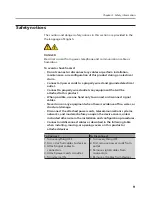
Safety notices ........................................................................................................ 9

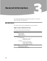
Chapter 3. General information ...........................................12

Specifications ..................................................................................................... 12

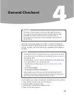
Chapter 4. General Checkout ...............................................13

Problem determination tips  ...................................................................... 14

Chapter 5. Using the Setup Utility ......................................16

Starting the Setup Utility program ......................................................... 16
Viewing and changing settings ................................................................ 16
Using passwords .............................................................................................. 17

Password considerations .................................................................................................. 17
Supervisor password .......................................................................................................... 17
User Password ........................................................................................................................ 18
Security Options ................................................................................................................... 19

Using Device ...................................................................................................... 20
Selecting a startup device ........................................................................... 20

Summary of Contents for IdeaCentre K210

Page 1: ...ng electrostatic discharge sensitive devices 8 Grounding requirements 8 Safety notices 9 Chapter 3 General information 12 Specifications 12 Chapter 4 General Checkout 13 Problem determination tips 14 Chapter 5 Using the Setup Utility 16 Starting the Setup Utility program 16 Viewing and changing settings 16 Using passwords 17 Password considerations 17 Supervisor password 17 User Password 18 Securi...

Page 2: ...omputer cover 28 Removing and replacing the front bezel 30 Replacing the power supply 31 Replacing the heat sink assembly 32 Replacing a memory module 33 Replacing an adapter 34 Replacing the hard disk drive 37 Replacing an optical drive 38 Replacing the system fan assembly 40 Replacing the keyboard 41 Replacing the mouse 42 Replacing the External speaker 43 Completing the installation 43 Chapter ...

Page 3: ...valid for those machines which do not have TV card Important Safety Information Be sure to read all caution and danger statements in this book before performing any of the instructions Veuillez lire toutes les consignes de type DANGER et ATTENTION du présent document avant d exécuter les instructions Lesen Sie unbedingt alle Hinweise vom Typ ACHTUNG oder VORSICHT in dieser Dokumentation bevor Sie ...

Page 4: ...2 Type the machine type Example 8129 in the Use Quick Path field then click Go 3 Under Browse by product click Continue 4 Under Important information click Parts information 5 In the Refine results field select Service parts then click the entry for your machine type The list of service parts by description with applicable machine type model and FRU part number is displayed Important information a...

Page 5: ...be used Products marketed before June 2006 Products marketed after June 2006 Current or original part Replacement FRU Current or original part Replacement FRU Non RoHS Can be Non RoHS Must be RoHS Must be RoHS Non RoHS Can be RoHS Non RoHS Can sub to RoHS RoHS Must be RoHS Note A direct substitution is a part with a different FRU part number that is automatically shipped by the distribution center...

Page 6: ... you think are too heavy for you Do not perform any action that causes hazards to the customer or that makes the equipment unsafe Before you start the machine ensure that other service representatives and the customer s personnel are not in a hazardous position Place removed covers and other parts in a safe place away from all personnel while you are servicing the machine Keep your tool case away ...

Page 7: ... electrical equipment Important Use only approved tools and test equipment Some hand tools have handles covered with a soft material that does not insulate you when working with live electrical currents Many customers have near their equipment rubber floor mats that contain small conductive fibers to decrease electrostatic discharges Do not use this type of mat to protect yourself from electrical ...

Page 8: ... instructions are in the safety sections of maintenance information Use extreme care when measuring high voltages Regularly inspect and maintain your electrical hand tools for safe operational condition Do not use worn or broken tools and testers Never assume that power has been disconnected from a circuit First check that it has been powered off Always look carefully for possible hazards in your ...

Page 9: ...ed CRT face or bulging capacitor Mechanical hazards such as loose or missing hardware The guide consists of a series of steps presented in a checklist Begin the checks with the power off and the power cord disconnected Checklist 1 Check exterior covers for damage loose broken or sharp edges 2 Power off the computer Disconnect the power cord 3 Check the power cord for a A third wire ground connecto...

Page 10: ...static on your body Prevent the part from touching your clothing Most clothing is insulative and retains a charge even when you are wearing a wrist strap Use the black side of a grounded work mat to provide a static free work surface The mat is especially useful when handling ESD sensitive devices Select a grounding system such as those listed below to provide protection that meets the specific se...

Page 11: ... hand only to connect or disconnect signal cables Never turn on any equipment when there is evidence of fire water or structural damage Disconnect the attached power cords telecommunications systems networks and modems before you open the device covers unless instructed otherwise in the installation and configuration procedures Connect and disconnect cables as described in the following table when...

Page 12: ...by local ordinances or regulations CAUTION When laser products such as CD ROMs DVD ROM drives fiber optic devices or transmitters are installed note the following Do not remove the covers Removing the covers of the laser product could result in exposure to hazardous laser radiation There are no serviceable parts inside the device Use of controls or adjustments or performance of procedures other th...

Page 13: ...he power supply do not turn off the electrical current supplied to the device The device also might have more than one power cord To remove all electrical current from the device ensure that all power cords are disconnected from the power source 1 2 CAUTION Do not place any object weighing more than 82 kg 180 lbs on top of rack mounted devices ...

Page 14: ...n lists the physical specifications for your computer Type Lenovo IdeaCentre K This section lists the physical specifications Dimensions Width 180 mm Height 388 mm Length 436 5 mm Environment Air temperature Operating 10 to 35 C Transit 40 to 55 C Humidity Operating 35 to 80 Transit 20 to 93 40 C Altitude 86KPa to 106KPa Electrical input Input voltage 220V 22V Input frequency 50Hz 1Hz ...

Page 15: ...uter to boot up in quiet mode no beep no memory count and checkpoint code display when no errors are detected by POST To enable beep memory count and checkpoint code display when a successful POST occurs do the following 1 Start the Setup Utility program See Starting the Setup Utility program 2 Select Start Options 3 Set Power On Self Test to Enhanced Before replacing any FRUs ensure that the late...

Page 16: ...on available when requesting assistance from Service Support and Engineering functions Machine type and model Processor or hard disk upgrades Failure symptom Do diagnostics indicate a failure What when where single or multiple systems Is the failure repeatable Has this configuration ever worked If it has been working what changes were made prior to it failing Is this the original reported failure ...

Page 17: ...Chapter 4 General Checkout 15 Comparing the configuration and software set up between working and non working systems will often lead to problem resolution ...

Page 18: ...s release the F1 key Notes a If you are using a USB keyboard and the Setup Utility program does not display using this method repeatedly press and release the F1 key rather than leaving it pressed when turning on the computer b If a user password or an administrator password has been set the Setup Utility program menu is not displayed until you type your password For more information see Using pas...

Page 19: ...e easily compromised We suggest the passwords should adhere to the following rules Must have at least seven characters in length Contain at least one alphabetic character one numeric character and one symbol Contain at least one of the following symbols You can also use the space bar Setup Utility program and hard disk drive passwords are not case sensitive Not be your name or your user name Not b...

Page 20: ...e a previously set supervisor password do the following Note When prompted for a password you must type your supervisor password 1 From the Setup Utility program menu select Change Supervisor Password and press Enter 2 when you type the supervisor password a message will display that Enter New Password Press Enter and a message will display that indicates the password has been disabled After that ...

Page 21: ...ss any key to contine Security Options After a Supervisor Password is set the Security Options can be displayed in the menu of Advanced BIOS Features To set Security Options do the following 1 Start the Setup Utility program See Starting the Setup Utility program 2 From the Setup Utility program menu selet Change Supervisor Password 3 Set the Supervisor Password 4 After that Select Advanced BIOS F...

Page 22: ...ct Discard Changes and Exit or Discard Changes You can set others such as OnBoard SiS USB2 0 Controller USB Keyboard Legacy Support USB Mouse Legacy Support Onboard Audio DEVICE Onboard LAN Control Boot from Onboard LAN and so on See the information displayed on the right side of the screen Selecting a startup device If your computer does not start up boot from a device such as the CD ROM diskette...

Page 23: ...the Setup Utility program on page 16 2 Select Advanced BIOS Features 3 Select the devices for the 1st Boot Device the 2nd Boot Device the 3rd Boot Deviece and the 4th Boot Device 4 Press ESC to return the Advanced BIOS Features and then Save changes and Exit If you have changed these settings and want to return to the default settings select Load Optimal Defaults on the Setup Utility menu Exiting ...

Page 24: ...iagnose the error message first If you cannot run the diagnostic tests or you get a diagnostic error code when running a test but did receive a POST error message diagnose the POST error message first If you did not receive any error message look for a description of your error symptoms in the first part of this index Hard disk drive boot error A hard disk drive boot error error codes 1962 and I99...

Page 25: ...k drive The drive is defective Replace the hard disk drive Power Supply Problems If you suspect a power problem use the following procedures Check Verify FRU Action Check the following for proper installation Power Cord On Off Switch connector On Off Switch Power Supply connector System Board Power Supply connectors Microprocessor s connection Reseat connectors Check the power cord for continuity ...

Page 26: ...malfunctioning add in card Remove all expansion cards except the video adapter If beep codes are generated when all other expansion cards are absent consult your system manufacturer s technical support If beep codes are not generated when all other expansion cards are absent one of the add in cards is causing the malfunction Insert the cards back into the system one at a time until the problem hap...

Page 27: ...the system one at a time until the problem happens again This will reveal the malfunctioning card 10 beeps CMOS shutdown register read write error 11 beeps Cache memory test failed POST error codes Each time you power on the system it performs a series of tests that check the operation of the system and some options This series of tests is called the Power On Self Test or POST POST does the follow...

Page 28: ...talled Primary Slave Hard Disk Error Secondary Master Hard Disk Error Secondary Slave Hard Disk Error PS2 Mouse not found PS2 Mouse support is enabled in the BIOS setup butthe device is not detected You can plug PS2 Mouse or set PS2 Mouse support is auto Keyboard error Cannot initialize the keyboard Make sure the keyboard is properly connected to the computer and that no keys are held pressed duri...

Page 29: ...ure that the hard disk drive is jumpered as a master and the optical drive is jumpered as a slave 1 Power off the computer 2 Remove or disconnect the following components if installed one at a time a External devices modem printer or mouse b Any adapters c Memory modules d Extended video memory e External Cache f External Cache RAM g Hard disk drive h Diskette drive 3 Power on the computer to re t...

Page 30: ...uter cover Important Turn off the computer and wait 3 to 5 minutes to let the computer cool before removing the computer cover To remove the computer cover 1 Remove any media diskettes CDs or tapes from the drives shut down your operating system turn off all attached devices and the computer 2 Unplug all power cords from electrical outlets 3 Disconnect all cables attached to the computer This incl...

Page 31: ...Chapter 7 Replacing hardware 29 5 Pull down the switch at the rear of the chassis and slide the computer cover to the rear to remove ...

Page 32: ...e computer cover 2 Remove the front bezel by releasing the three plastic tabs inside the chassis and push the bezel outward as shown 3 To reinstall the bezel align the plastic tabs on the bottom of the bezel with the corresponding holes in the chassis then snap it into position at the bottom and top of the chassis 4 Refer to the Completing the installation ...

Page 33: ...e the computer cover Refer to Removing the computer cover Note For this procedure it helps to lay the computer on its side 2 Disconnect the power supply cables from the system board and from all drives Refer to Identifying parts on the system board 3 Remove the four screws that secure the power supply at the rear of the chassis 4 Lift the power supply out of the chassis 5 Install the new power sup...

Page 34: ...or HMM go to the Support Web site at http www lenovo com support To replace the heat sink assembly 1 Remove the computer cover Refer to Removing the computer cover 2 Lay the computer on its side 3 Locate the heat sink Refer to Identifying parts on the system board 4 Disconnect the heat sink and the fan assembly cable from the system board 5 Remove the four screws securing the heat sink and fan ass...

Page 35: ...in the Safety and Warranty Guide that was included with your computer or in the Hardware Maintenance Manual HMM for the computer To obtain copies of the Safety and Warranty Guide or HMM go to the Support Web site at http www lenovo com support To replace a memory module 1 Remove the computer cover Refer to Removing the computer cover Note For this procedure it helps to lay the computer on its side...

Page 36: ...puter cover or attempt any repair before reading the Important safety information in the Safety and Warranty Guide that was included with your computer or in the Hardware Maintenance Manual HMM for the computer To obtain copies of the Safety and Warranty Guide or HMM go to the Support Web site at http www lenovo com support To replace an adapter 1 Remove the computer cover Refer to Removing the co...

Page 37: ...Replacing hardware 35 3 Install the new adapter into the same adapter connector 4 Ensure the adapter is fully seated into the adapter connector 5 At the rear of the computer pivot the adapter latch to the closed ...

Page 38: ... screws that secure the bracket at the bottom of the chassis 2 Lift the bracket out of the chassis 3 Then remove the adapter as above After the Graphic Adapter is installed install the bracket as the following 1 Install the bracket into the chassis so that the screw holes in the bracket align with those in the chassis Let the slot on the bracket clip the adapter 2 Install the two screws to secure ...

Page 39: ...b site at http www lenovo com support Important When you receive a new hard disk drive you will also receive a set of Operating System Recovery CD The set of Operating System Recovery CD will enable you to restore the Operating System of the hard disk For more information on recovering factory installed software refer to OneKey Recovery in the User Guide To replace the hard disk drive 1 Remove the...

Page 40: ...ove the computer cover or attempt any repair before reading the Important safety information in the Safety and Warranty Guide that was included with your computer or in the Hardware Maintenance Manual HMM for the computer To obtain copies of the Safety and Warranty Guide or HMM go to the Support Web site at http www lenovo com support To replace an optical drive 1 Remove the computer cover Refer t...

Page 41: ...ve out the front of the computer 5 Slide the new optical drive into the bay from the front until it snap into position 6 Connect the signal and power cables to the drive 7 Install the front bezel Refer to Removing and replacing the front bezel 8 Refer to the Completing the installation ...

Page 42: ...go to the Support Web site at http www lenovo com support To replace the system fan assembly 1 Remove the computer cover Refer to Removing the computer cover 2 Locate the system fan assembly Refer to Identifying parts on the system board 3 Disconnect the system fan assembly cable from the system board Refer to Identifying parts on the system board 4 Pull the system fan assembly out of chassis 5 In...

Page 43: ...omputer cover or attempt any repair before reading the Important safety information in the Safety and Warranty Guide that was included with your computer or in the Hardware Maintenance Manual HMM for the computer To obtain copies of the Safety and Warranty Guide or HMM go to the Support Web site at http www lenovo com support To replace the keyboard 1 Remove any media diskettes CDs or tapes from t...

Page 44: ...empt any repair before reading the Important safety information in the Safety and Warranty Guide that was included with your computer or in the Hardware Maintenance Manual HMM for the computer To obtain copies of the Safety and Warranty Guide or HMM go to the Support Web site at http www lenovo com support To replace the mouse 1 Remove any media diskettes CDs or tapes from the drives shut down you...

Page 45: ...omputer Your speaker might be connected to the Audio connector to an Audio connector at either the front or rear of the computer Locate the connector for the speaker 4 Disconnect the failing speaker cable from the computer and connect the new speaker cable to the same connector 5 Refer to the Completing the parts replacement Completing the installation After replacing the parts you need to close t...

Page 46: ... of the computer cover engage the rails Then push the computer cover closed until it snaps into position 4 If a cover lock is installed lock the cover 5 Reconnect the external cables and power cords into the computer Refer to Locating connectors on the front of the computer and Locating connectors on the rear of the computer 6 To update your configuration settings refer to Starting the Setup Utili...

Page 47: ...for Advanced Power Management APM BIOS mode is ignored Not all operating systems support ACPI BIOS mode Automatic Power On features The Automatic Power On features within the Power Management menu allow you to enable and disable features that turn on the computer automatically Resume On Ring With this feature set to Enabled the computer will turn on automatically when a ring is detected on the int...

Page 48: ...e programs described in all the manuals included with your computer and the content of the manual at any time without additional notice All the manuals included with your computer is provided to help you use Lenovo products appropriately but it does not represent any description of the software hardware configuration for the product For the configuration of the product refer to related contract if...

Page 49: ...ks of Advanced Micro Devices This is description of trademarks or registered trademarks of Lenovo and its partners Other registered trademarks mentioned in all the manuals included with your computer belong to the specific company respectively All rights reserved All the manuals included with your computer is protected by copyright laws Any part of all the manuals included with your computer may n...

Reviews: