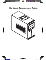
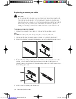
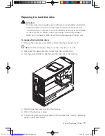
background image

www.lenovo.com

IdeaCentre K3

Hardware Replacement Guide

Version 1.0

2009.8

31037823

31037823_K3_HRG_FM_EN_V1.0.indd   1

2009.7.23   9:31:25 AM

Summary of Contents for IDEACENTRE K3

Page 1: ...www lenovo com IdeaCentre K3 Hardware Replacement Guide Version 1 0 2009 8 31037823 31037823_K3_HRG_FM_EN_V1 0 indd 1 2009 7 23 9 31 25 AM ...

Page 2: ...Hardware Replacement Guide 31037823_K3_HRG_EN_V1 0 indd 1 2009 8 4 4 43 01 PM ...

Page 3: ...he front bezel 11 Replacing a memory module 12 Replacing the hard disk drive 13 Replacing an optical drive 14 Replacing the system fan assembly 15 Replacing the heat sink assembly 18 Replacing a PCI or AGP adapter 20 Replacing the CPU 26 Replacing the keyboard 29 Replacing the mouse 30 Replacing the External speaker 31 Completing the installation 31 Appendix 33 31037823_K3_HRG_EN_V1 0 indd 2 2009 ...

Page 4: ...arts provided by Lenovo The description of the TV Tuner card in this manual applies only to those computer models that have the TV Tuner card installed It does not apply to those computer models that do not have the TV Tuner card installed This guide contains procedures for replacing the following parts Memory modules Hard disk drive Optical drive Heatsink Fan CPU VGA card Keyboard Mouse wired Ext...

Page 5: ...iver Hex screwdriver Plastic flat screwdriver Plastic tweezers Note The screws for the different components vary in size During the disassembly procedure group the screws with their corresponding components to avoid a mismatch when replacing the components Handling static sensitive devices Static electricity although harmless to you can seriously damage computer components When you are replacing a...

Page 6: ...to a metal expansion slot cover or other unpainted metal surface on the computer for at least two seconds This reduces static electricity in the package and your body When possible remove the new part from the static protective packaging and install it directly in the computer without setting the part down When this is not possible place the static protective package that the part came in on a smo...

Page 7: ...o remove the computer cover refer to Removing the computer cover Locating components and connectors The following illustrations will help you to locate the various components and connectors in your computer Internal components The following illustration shows the components inside your computer 1 3 2 4 5 6 7 8 31037823_K3_HRG_EN_V1 0 indd 4 2009 8 4 4 43 03 PM ...

Page 8: ...adapter connector Optical drive Front view The following illustrations show the location of connectors on the front of the computer 9 8 3 1 2 4 5 6 7 Power button Power Dial indicator ON OFF File backup button USB connector Microphone connector Headphone connector Memory card reader selected models only 31037823_K3_HRG_EN_V1 0 indd 5 2009 8 4 4 43 04 PM ...

Page 9: ...on the rear of the computer 8 11 12 13 14 9 10 7 1 2 3 4 5 6 Voltage selection switch selected models only Power connector PS 2 keyboard connector PS 2 mouse connector Serial connector On board VGA connector selected models only USB connectors 6 Ethernet connector Microphone connector Audio line out connector Audio line in connector 31037823_K3_HRG_EN_V1 0 indd 6 2009 8 4 4 43 06 PM ...

Page 10: ...s 802 11b g Wireless PCI E Adapter Card User Manual TV Tuner selected models only Identifying parts on the system board The system board sometimes called the planar or motherboard is the main circuit board in your computer It provides basic computer functions and supports a variety of devices that are factory installed or that you can install later The following illustrations show the locations of...

Page 11: ...er fan connector SATA IDE connectors 4 Front panel connector Front USB connectors 2 Serial com2 connector Front audio connector PCI adapter connector PCI Express x1 adapter connectors 2 PCI Express x16 graphics adapter connector System fan connector 12V power connector 31037823_K3_HRG_EN_V1 0 indd 8 2009 8 4 4 43 07 PM ...

Page 12: ...fore proceeding with the disassembly procedure make sure that you do the following 1 Turn off the power to the system and all peripherals 2 Unplug all power and signal cables from the computer 3 Place the system on a flat stable surface Removing the computer cover Attention Turn off the computer and wait 3 to 5 minutes to let the computer cool before removing the computer cover To remove the compu...

Page 13: ...hat are connected to the computer Refer to Locating connectors on the rear of the computer 4 Remove the two screws that secure the computer cover at the rear of the chassis 5 Slide the computer cover to the rear of the chassis to remove Note For this procedure it helps to lay the computer on its side 31037823_K3_HRG_EN_V1 0 indd 10 2009 8 4 4 43 16 PM ...

Page 14: ...ts side 2 Remove the front bezel by releasing the three plastic tabs inside the chassis and push the bezel outward as shown 3 To reinstall the bezel align the plastic tabs on the bottom of the bezel with the corresponding holes in the chassis and then snap it into position at the bottom and top of the chassis 4 Refer to the Completing the installation 31037823_K3_HRG_EN_V1 0 indd 11 2009 8 4 4 43 ...

Page 15: ...a memory module 1 Remove the computer cover Refer to Removing the computer cover Note For this procedure it helps to lay the computer on its side 2 Locate the memory module connectors Refer to Locating components 3 Remove the memory module being replaced by opening the retaining clips as shown 4 Position the new memory module over the memory connector Make sure the notch on the memory aligns corre...

Page 16: ...ite at http consumersupport lenovo com To replace the hard disk drive 1 Remove the computer cover Refer to Removing the computer cover Note For this procedure it helps to lay the computer on its side 2 Disconnect the data and power cables from the hard disk drive 3 Use the plastic handle to slide the hard disk drive out of the drive bay 4 Slide the new hard disk drive into the drive bay 5 Pivot in...

Page 17: ...nual HMM for the computer To obtain copies of the Safety and Warranty Guide or HMM go to the Support Web site at http consumersupport lenovo com To replace an optical drive 1 Remove the computer cover Refer to Removing the computer cover 2 Remove the front bezel Refer to Removing the front bezel 3 Disconnect the data and power cables from the rear of the optical drive 4 Press the release button an...

Page 18: ... the Important safety information in the Safety and Warranty Guide that was included with your computer or in the Hardware Maintenance Manual HMM for the computer To obtain copies of the Safety and Warranty Guide or HMM go to the Support Web site at http consumersupport lenovo com To replace the system fan assembly 1 Remove the computer cover Refer to Removing the computer cover 2 Locate the syste...

Page 19: ...16 Hardware Replacement Guide 4 Pull the system fan assembly out of chassis 31037823_K3_HRG_EN_V1 0 indd 16 2009 8 4 4 43 46 PM ...

Page 20: ...h the holes on the chassis and push the rubber mounts through the holes 6 Pull on the tips of the rubber mounts until the fan assembly is in place 7 Connect the system fan assembly cable to the system fan connector on the system board 8 Refer to the Completing the installation 31037823_K3_HRG_EN_V1 0 indd 17 2009 8 4 4 43 54 PM ...

Page 21: ...the heat sink assembly 1 Remove the computer cover Refer to Removing the computer cover 2 Lay the computer on its side 3 Locate the heat sink Refer to Identifying parts on the system board 4 Disconnect the heat sink and the fan assembly cable from the system board 5 Remove the four screws securing the heat sink and fan assembly to the system board 6 Lift the failing heat sink and fan assembly off ...

Page 22: ...e 8 Install the heat sink and fan assembly on the heat sink retention bracket 9 Reconnect the disconnected cables to the system board 10 Refer to the Completing the installation 31037823_K3_HRG_EN_V1 0 indd 19 2009 8 4 4 44 04 PM ...

Page 23: ...dware Maintenance Manual HMM for the computer To obtain copies of the Safety and Warranty Guide or HMM go to the Support Web site at http consumersupport lenovo com To replace an adapter 1 Remove the computer cover Refer to Removing the computer cover 2 At the rear of the computer press the release button to open the adapter latch and remove the adapter by pulling it straight out of the adapter co...

Page 24: ...apter connector 4 Ensure the adapter is fully seated into the adapter connector 5 At the rear of the computer pivot the adapter latch to the closed position to secure the adapter 6 Refer to the Completing the installation 31037823_K3_HRG_EN_V1 0 indd 21 2009 8 4 4 44 07 PM ...

Page 25: ...racket at the bottom of the chassis 2 Lift the plastic bracket out of the chassis 3 Then remove the adapter as above After the Graphic Adapter is installed install the bracket as the following 1 Install the plastic bracket into the chassis so that the screw holes in the plastic bracket align with those in the chassis Let the slot on the plastic bracket clip the adapter 31037823_K3_HRG_EN_V1 0 indd...

Page 26: ...23 Hardware Replacement Guide 2 Install the two screws to secure the plastic bracket Note Use only the screws provided by Lenovo 31037823_K3_HRG_EN_V1 0 indd 23 2009 8 4 4 44 14 PM ...

Page 27: ...of the chassis 2 Press the pin on one end of the metal bracket and pull the metal bracket straight out of the chassis After the Graphic Adapter is installed install the bracket as the following 1 Install the metal bracket into the chassis so that the screw hole in the metal bracket aligns with the hole in the chassis Let the slot on the metal bracket clip the adapter 31037823_K3_HRG_EN_V1 0 indd 2...

Page 28: ...25 Hardware Replacement Guide 2 Screw back the screws on the metal bracket Note Use only the screw provided by Lenovo 31037823_K3_HRG_EN_V1 0 indd 25 2009 8 4 4 44 39 PM ...

Page 29: ...rsupport lenovo com To replace an CPU 1 Remove the computer cover Refer to Removing the computer cover 2 Remove the front bezel Refer to Removing the front bezel 3 Remove the system board Refer to Replacing the heat sink assembly 4 Remove the heat sink and fan assembly Refer to Replacing the heat sink assembly 5 To remove the microprocessor from the system board lift the small handle and open the ...

Page 30: ...oprocessor on the new system board b Do not drop anything onto the microprocessor socket while it is exposed The socket pins must be kept as clean as possible 7 Make sure that the microprocessor retainer is fully open 8 Holding the microprocessor with your fingers remove the protective cover that protects the gold contacts on the new microprocessor 31037823_K3_HRG_EN_V1 0 indd 27 2009 8 4 4 44 49 ...

Page 31: ... with the small handle 12 Use the thermal grease syringe to place five drops of grease on the top of the microprocessor Each drop of grease should be 0 03ml 3 tick marks on the grease syringe 13 Install the heat sink and fan assembly on the system board 14 Connect the heat sink and fan assembly cable to the system board Refer to the Identifying parts on the system board 15 Install the system board...

Page 32: ...r the keyboard Refer to Locating connectors on the rear of the computer and Locating connectors on the front of the computer Note Your keyboard might be connected to the standard keyboard connector at the rear of the computer or to a USB connector at either the front or rear of the computer 4 Disconnect the failing keyboard cable from the computer and connect the new keyboard cable to the same con...

Page 33: ...ector for the mouse Refer to Locating connectors on the front of the computer and Locating connectors on the rear of the computer Note Your mouse might be connected to the standard mouse connector at the rear of the computer or to a USB connector at either the front or rear of the computer 4 Disconnect the failing mouse cable from the computer 5 Connect the new mouse cable to the connector 6 Refer...

Page 34: ...nect the new speaker cable to the same connector Completing the installation After replacing the parts you need to close the computer cover and reconnect cables including telephone lines and power cords Also depending on the part that was replaced you might need to confirm the updated information in the Setup Utility program Refer to Starting the Setup Utility in the User Guide or in the Hardware ...

Page 35: ... computer Refer to Locating connectors on the front of the computer and Locating connectors on the rear of the computer 5 To update your configuration settings refer to Starting the Setup Utility in the User Guide or in the Hardware Maintenance Manual Note In most areas of the world Lenovo requires the return of the defective CRU Information about this will come with the CRU or will come a few day...

Page 36: ... included with your computer are provided to help you use Lenovo products appropriately but do not provide any description of the software hardware configuration for the product For the configuration of the product refer to related contract if any product packing list for the product or retailer The content of the manuals included with your computer is protected by copyright laws and rules None of...

Page 37: ...her registered trademarks mentioned in all the manuals included with your computer belong to the specific company respectively The manual included with your computer is protected by copyright laws and rules None of the manuals included with your computer may be reproduced or transcribed by any means or transmitted through wired or wireless network in any form or translated into any language withou...

Reviews: