44
Lenovo ideapad 310S-14AST/ideapad 510S-14ISK/
ideapad 310S-14ISK Hardware Maintenance Manual
1080 Fan and heat sink assembly
For access, remove these FRUs in order:
•
“1010 Base cover” on page 32
•
“1020 Battery pack” on page 34
•
“1050 PCI Express Mini Card for wireless LAN” on page 38
•
“1060 Upper case” on page 41
•
“1070 DC-in cable” on page 43
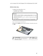
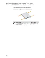
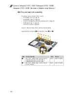
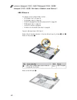
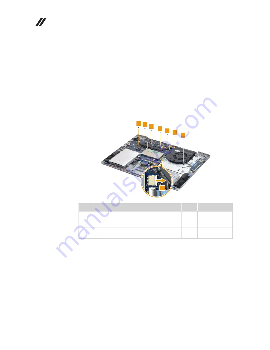
Figure 8. Removal steps of fan and heat sink assembly
Unplug the fan connector
1
. Remove the screws
2
and
3
.
2
2
2 2
2
3
3
1
Step Screw (quantity)
Color Torque
2
M2 × 3 mm, Phillips head, nylok-coated (5)
THERMAL MODULE TO CPU BRK &
THERMAL MODULE TO GPU (DIS)
Black
1.85±0.15 kgf*cm
3
M2 × 4 mm, Phillips head, nylok-coated (2)
FAN TO UPPER
Silver
1.85±0.15 kgf*cm


