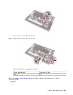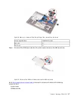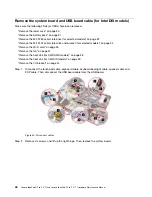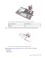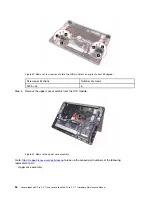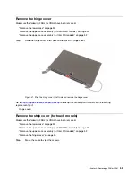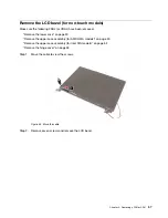
Figure 34. Disconnect antennas and EDP cable
Step 3. Remove six screws. Then, rotate the LCD module to an angle of about 90 degrees and place the
computer on a flat surface.
Figure 35. Remove six screws and rotate the LCD module to an angle of about 90 degrees
Screw specifications
Number of screws
M2.5 × L4
6
Step 4. Remove the upper case assembly from the LCD module.
.
51
Summary of Contents for IdeaPad 5 Pro
Page 1: ...Lenovo IdeaPad 5i Pro 14 7 and Lenovo IdeaPad 5 Pro 14 7 Hardware Maintenance Manual ...
Page 2: ...First Edition March 2022 Copyright Lenovo 2022 ...
Page 4: ...ii Lenovo IdeaPad 5i Pro 14 7 and Lenovo IdeaPad 5 Pro 14 7 Hardware Maintenance Manual ...
Page 6: ...iv Lenovo IdeaPad 5i Pro 14 7 and Lenovo IdeaPad 5 Pro 14 7 Hardware Maintenance Manual ...
Page 11: ...DANGER DANGER DANGER DANGER DANGER Chapter 1 Safety information 5 ...
Page 12: ...6 Lenovo IdeaPad 5i Pro 14 7 and Lenovo IdeaPad 5 Pro 14 7 Hardware Maintenance Manual ...
Page 13: ...PERIGO PERIGO PERIGO Chapter 1 Safety information 7 ...
Page 15: ...DANGER DANGER DANGER DANGER Chapter 1 Safety information 9 ...
Page 17: ...VORSICHT VORSICHT VORSICHT VORSICHT Chapter 1 Safety information 11 ...
Page 19: ...Chapter 1 Safety information 13 ...
Page 20: ...14 Lenovo IdeaPad 5i Pro 14 7 and Lenovo IdeaPad 5 Pro 14 7 Hardware Maintenance Manual ...
Page 21: ...Chapter 1 Safety information 15 ...
Page 22: ...16 Lenovo IdeaPad 5i Pro 14 7 and Lenovo IdeaPad 5 Pro 14 7 Hardware Maintenance Manual ...
Page 23: ...Chapter 1 Safety information 17 ...
Page 24: ...18 Lenovo IdeaPad 5i Pro 14 7 and Lenovo IdeaPad 5 Pro 14 7 Hardware Maintenance Manual ...
Page 25: ...Chapter 1 Safety information 19 ...
Page 26: ...20 Lenovo IdeaPad 5i Pro 14 7 and Lenovo IdeaPad 5 Pro 14 7 Hardware Maintenance Manual ...
Page 34: ...28 Lenovo IdeaPad 5i Pro 14 7 and Lenovo IdeaPad 5 Pro 14 7 Hardware Maintenance Manual ...
Page 76: ......
Page 77: ......
Page 78: ......

