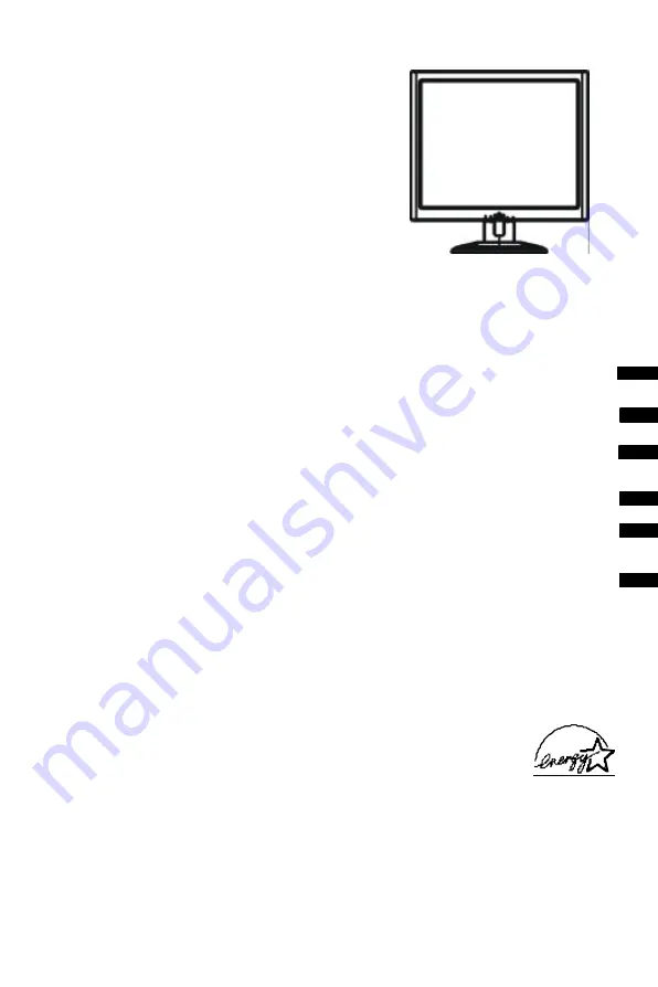
LXB-L17C
USER MANUAL
TABLE OF CONTENTS
FOR YOUR SAFETY -------------------------------------------------- 1
SAFETY PRECAUTIONS -------------------------------------- 2
SPECIAL NOTES ON LCD MONITORS ------------------- 3
BEFORE YOU OPERATE THE MONITOR --------------------- 3
FEATURES -------------------------------------------------------- 3
PACKING LIST --------------------------------------------------- 3
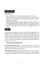
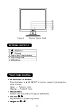
CONTROLS AND CONNECTORS ----------------------- 4-5
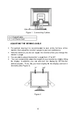
ADJUSTING THE VIEWING ANGLE --------------------
5-6
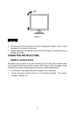
OPERATING INSTRUCTIONS ------------------------------------- 7
GENERAL INSTRUCTIONS ---------------------------------- 8
HOW TO ADJUST A SETTING ------------------------------ 9
ADJUSTING THE PICTURE ------------------------------
9-10
PLUG AND PLAY -----------------------------------------------
11
TECHNICAL SUPPORT(FAQ) -------------------------------
12-13
ERROR MESSAGE & POSSIBLE SOLUTION -------
14
APPENDIX --------------------------------------------------------------
15
SPECIFICATIONS -----------------------------------------
15-16
FACTORY PRESET TIMING TABLE ----------------------
17
CONNECTOR PIN ASSIGNMENT -------------------------
17
English
Deutsch
Françai
Español
Italian
TCO’95